
FAN7171_F085 - Fairchild Semiconductor
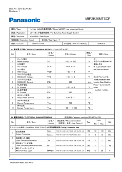
FAN7171_F085 High-Current High-Side Gate Drive IC Features Description Automotive qualified to AEC Q100 The FAN7171_F085 is a monolithic high-side gate drive IC that can drive high-speed MOSFETs and IGBTs that operate up to +600 V. It has a buffered output stage with all NMOS transistors designed for high pulse current driving capability and minimum cross-conduction. Common-Mode dv/dt Noise-Cancelling Circuit Floating Channel for Bootstrap Operation to +600 V 4 A Sourcing and 4 A Sinking Current Driving Capability 3.3 V and 5 V Input Logic Compatible Output In-phase with Input Signal Under- Voltage Lockout for VBS 25 V Shunt Regulator on VDD and VBS The UVLO circuit prevents malfunction when VBS is lower than the specified threshold voltage. 8-Lead, Small Outline Package The high-current and low-output voltage-drop feature make this device suitable for sustaining switch drivers and energy-recovery switch drivers in automotive motor drive inverters, switching power supplies, and highpower DC-DC converter applications. Applications Fairchild’s high-voltage process and common-mode noise-canceling techniques provide stable operation of the high-side driver under high-dv/dt noise circumstances. An advanced level-shift circuit offers high-side gate driver operation up to VS=-9.8 V (typical) for VBS=15 V. Common Rail Injection Systems DC-DC Converter Motor Drive (Electric Power Steering, Fans) Related Product Resources FAN7171_F085 Product Folder AN-8102 200 Recommendations to Avoid Short Pulse Width Issues in HVIC Gate Driver Applications AN-9052 Design Guide for Selection of Bootstrap Components AN-4171 FAN7085 High-Side Gate Driver- Internal Recharge Path Design Considerations AN-6076 Design and Application Guide of Bootstrap Circuit for High-Voltage Gate-Drive IC Figure 1. 8-Lead, SOIC, Narrow Body Ordering Information Part Number FAN7171M_F085 FAN7171MX_F085 Operating Temperature Range Package Packing Method -40°C ~ 125°C 8-Lead, Small Outline Integrated Circuit (SOIC), JEDEC MS-012, .150 inch Narrow Body Tube Tape & Reel Note: 1. These devices passed wave soldering test by JESD22A-111. © 2012 Fairchild Semiconductor Corporation FAN7171_F085 • Rev. 1.0.2 www.fairchildsemi.com FAN7171_F085 — High-Current High-Side Gate Drive IC November 2014 FAN7171_F085 — High-Current High-Side Gate Drive IC Typical Application Figure 2. Typical Application Block Diagram Figure 3. Block Diagram Pin Configuration Figure 4. Pin Assignment (Top Through View) Pin Descriptions Pin # Name 1 VDD 2 IN Logic Input for High-Side Gate Driver Output 3 NC No Connection 4 GND 5 NC No Connection 6 VS High-Voltage Floating Supply Return 7 HO High-Side Driver Output 8 VB High-Side Floating Supply © 2012 Fairchild Semiconductor Corporation FAN7171_F085 • Rev. 1.0.2 Description Supply Voltage Ground www.fairchildsemi.com 2 Stresses exceeding the absolute maximum ratings may damage the device. The device may not function or be operable above the recommended operating conditions and stressing the parts to these levels is not recommended. In addition, extended exposure to stresses above the recommended operating conditions may affect device reliability. The absolute maximum ratings are stress ratings only. Symbol VS Characteristics High-Side Floating Offset Voltage (2) Min. Max. Unit VB-VSHUNT VB+0.3 V VB High-Side Floating Supply Voltage -0.3 625.0 V VHO High-Side Floating Output Voltage VS-0.3 VB+0.3 V VDD Low-Side and Logic Supply Voltage(2) -0.3 VSHUNT V VIN Logic Input Voltage -0.3 VDD+0.3 V dVS/dt Allowable Offset Voltage Slew Rate ±50 V/ns 0.625 W 200 °C/W -55 150 °C Storage Temperature -55 150 °C Operating Ambient Temperature -40 125 °C PD Power Dissipation(3,4,5) θJA Thermal Resistance TJ Junction Temperature TSTG TA ESD Human Body Model (HBM) 1500 Charge Device Model (CDM) 500 V Notes: 2. This IC contains a shunt regulator on VDD and VBS with a normal breakdown voltage of 25 V. Please note that this supply pin should not be driven by a low-impedance voltage source greater than the VSHUNT specified in the Electrical Characteristics section. 3. Mounted on 76.2 x 114.3 x 1.6 mm PCB (FR-4 glass epoxy material). 4. Refer to the following standards: JESD51-2: Integral circuits thermal test method environmental conditions, natural convection, and JESD51-3: Low effective thermal conductivity test board for leaded surface-mount packages. 5. Do not exceed power dissipation (PD) under any circumstances. Recommended Operating Conditions The Recommended Operating Conditions table defines the conditions for actual device operation. Recommended operating conditions are specified to ensure optimal performance. Fairchild does not recommend exceeding them or designing to Absolute Maximum Ratings. Symbol VBS VS Parameter Min. Max. Unit High-Side Floating Supply Voltage VS+10 VS+20 V High-Side Floating Supply Offset Voltage (DC) 6-VDD 600 V VS VB V GND VDD V 10 20 V High-Side Floating Supply Offset Voltage (Transient) VHO High-Side Output Voltage VIN Logic Input Voltage VDD Supply Voltage © 2012 Fairchild Semiconductor Corporation FAN7171_F085 • Rev. 1.0.2 -15 (~170) -7 (~400) www.fairchildsemi.com 3 FAN7171_F085 — High-Current High-Side Gate Drive IC Absolute Maximum Ratings VBIAS (VDD, VBS)=15 V, -40°C ≤ TA ≤ 125°C, unless otherwise specified. The VIN and IIN parameters are referenced to GND. The VO and IO parameters are relative to VS and are applicable to the respective output HO. Symbol Parameter Conditions Min. Typ. Max. Unit Power Supply Section IQDD Quiescent VDD Supply Current VIN=0 V or 5 V 25 70 μA IPDD Operating VDD Supply Current fIN=20 kHz, No Load 35 100 μA Bootstrapped Supply Section VBSUV+ VBS Supply Under-Voltage Positive-Going Threshold Voltage VBS=Sweep 8.2 9.2 10.2 V VBSUV- VBS Supply Under-Voltage Negative-Going Threshold Voltage VBS=Sweep 7.5 8.5 9.5 V VBSHYS VBS Supply UVLO Hysteresis Voltage VBS=Sweep ILK Offset Supply Leakage Current VB=VS=600 V IQBS Quiescent VBS Supply Current VIN=0 V or 5 V IPBS Operating VBS Supply Current CLOAD=1 nF, fIN=20 kHz, RMS Value 0.6 V 50 μA 60 120 μA 0.73 2.80 mA Shunt Regulator Section VSHUNT VDD and VBS Shunt Regulator Clamping Voltage ISHUNT=5 mA 23 25 V Input Logic Section (IN) VIH Logic “1” Input Voltage 2.5 VIL Logic “0” Input Voltage IIN+ Logic Input High Bias Current VIN=5 V IIN- Logic Input Low Bias Current VIN=0 V RIN Input Pull-down Resistance V 45 40 0.8 V 125 μA 2 μA 110 kΩ Gate Driver Output Section (HO) VOH High Level Output Voltage (VBIAS - VO) No Load 1.5 V VOL Low Level Output Voltage No Load 35 mV IO+ Output High, Short-Circuit Pulsed Current(6) VHO=0 V, VIN=5 V, PW ≤10 µs 3.0 4.0 A IO- Output Low, Short-Circuit Pulsed Current(6) VHO=15 V,VIN=0 V, PW ≤10 µs 3.0 4.0 A VS Allowable Negative VS Pin Voltage for IN Signal Propagation to HO -9.8 -7.0 V Typ. Max. Unit Note: 6. These parameters guaranteed by design. Dynamic Electrical Characteristics VBIAS (VDD, VBS) =15 V, VS=GND=0 V, CL=1000 pF, and-40°C ≤ TA ≤ 125°C, unless otherwise specified. Symbol Parameter Conditions Min. tON Turn-On Propagation Delay VS=0 V 150 210 ns tOFF Turn-Off Propagation Delay VS=0 V 150 210 ns tR Turn-On Rise Time 25 50 ns tF Turn-Off Fall Time 15 45 ns © 2012 Fairchild Semiconductor Corporation FAN7171_F085 • Rev. 1.0.2 www.fairchildsemi.com 4 FAN7171_F085 — High-Current High-Side Gate Drive IC Electrical Characteristics Figure 5. Figure 7. Figure 9. Turn-On Propagation Delay vs. Temperature Figure 6. Turn-On Rise Time vs. Temperature Figure 8. Operating VDD Supply Current vs. Temperature © 2012 Fairchild Semiconductor Corporation FAN7171_F085 • Rev. 1.0.2 Figure 10. Turn-Off Propagation Delay vs. Temperature Turn-Off Fall Time vs. Temperature Operating VBS Supply Current vs. Temperature www.fairchildsemi.com 5 FAN7171_F085 — High-Current High-Side Gate Drive IC Typical Performance Characteristics Figure 11. Figure 13. VBS UVLO+ vs. Temperature Figure 12. Logic High Input Voltage vs. Temperature Figure 14. Figure 15. Input Pull-Down Resistance vs. Temperature © 2012 Fairchild Semiconductor Corporation FAN7171_F085 • Rev. 1.0.2 VBS UVLO- vs. Temperature Logic Low Input Voltage vs. Temperature Figure 16. High-Level Output Voltage vs. Temperature www.fairchildsemi.com 6 FAN7171_F085 — High-Current High-Side Gate Drive IC Typical Performance Characteristics Figure 17. Output High, Short-Circuit Pulsed Current Figure 18. vs. Temperature Output Low, Short-Circuit Pulsed Current vs. Temperature Figure 19. Output High, Short-Circuit Pulsed Current Figure 20. vs. Supply Voltage Output Low, Short-Circuit Pulsed Current vs. Supply Voltage Figure 21. Quiescent VDD Supply Current vs. Supply Voltage © 2012 Fairchild Semiconductor Corporation FAN7171_F085 • Rev. 1.0.2 Figure 22. Quiescent VBS Supply Current vs. Supply Voltage www.fairchildsemi.com 7 FAN7171_F085 — High-Current High-Side Gate Drive IC Typical Performance Characteristics FAN7171_F085 — High-Current High-Side Gate Drive IC Switching Time Definitions Figure 23. Switching Time Test Circuit (Referenced 8-SOIC) Figure 24. Switching Time Waveform Definitions Figure 25. Abnormal Output Waveform with Short Pulse Width Figure 26. Recommendation of Pulse Width Output Waveform © 2012 Fairchild Semiconductor Corporation FAN7171_F085 • Rev. 1.0.2 www.fairchildsemi.com 8
© Copyright 2024