
ZAJ-065・ZAJ-123 シリーズ
取扱説明書
エア駆動油圧ポンプ
書類番号
書類改訂版
書類改訂日
L4091
A
08/2014
A で始まる製品
日付コード用
A
Z AJ-065 ・ZAJ-123 シ リーズ
INDEX
日本語取扱説明書・部品表
English Instruction Sheet
English Repair Parts Sheet
PAGE
1-31
32-54
55-74
取扱説明書
書類番号
書類改訂版
書類改訂日
A で始まる製品
日付コード用
L4091
A
08/2014
A
ZAJ -0 6 5 ・ ZAJ-123 シリーズ
I N D EX
1.0
2.0
3.0
3.1
3.2
3.3
3.4
3.5
3.6
3.7
3.8
3.9
3.10
4.0
4.1
4.2
4.3
4.4
4.5
4.6
4.7
4.8
4.9
5.0
5.1
5.2
5.3
5.4
5.5
5.6
5.7
5.8
5.9
5.10
5.11
6.0
7.0
8.0
製品受取時の注意
安全注意事項
使用方法
配管と圧力計の接続
ポンプの圧力調整
エア供給ラインの接続
リザーバー油量の点検
油圧回路内のエア抜き
ポンプ駆動前の点検
ポンプ型式と仕様
ポ ン プ 吐 出 量 曲 線 と エ ア 消 費量曲線
Z A J 型 エ ア 駆 動 油 圧 ポ ン プ 基本油圧回路
Z A J 型 エ ア 駆 動 油 圧 ポ ン プ 応用油圧回路
標 準 型 式 ポ ン プ の 機 能 と 使 用方法
Z A J 06505- M 1 ・ Z A J 12305- M 1( P.R 取出しブロック付ポンプ)
Z A J 06505- M 3 ・Z A J 12305- M 3( 手動3方弁付ポンプ)
Z A J 06505- M 32 ・ Z A J 12305- M 3 2( 手動3方弁付ポンプ)
Z A J 06505- M 4 ・Z A J 12305- M 4( 手動4方弁付ポンプ)
Z A J 06505- S 1 ・Z A J 12305- S 1( 電磁操作3方弁付ポンプ)
Z A J 06505- S 2 ・Z A J 12305- S 2( 電磁操作3方弁 ×2個付ポンプ)
ZAJ06505-C2・Z A J 12305- C 2( 電磁操作3方弁 ×2個付ポンプ)
ZAJ06505-A1・Z A J 1 2 3 0 5 - A 1( エアオペレート3方弁付ポンプ)
ZAJ06505-A2・Z A J 1 2 3 0 5 - A 2( エアオペレート3方弁 ×2個付ポンプ)
定期点検・整備
毎日の点検
毎週の点検
毎月の点検
作動油の交換方法
作 動 油 の 劣 化 状 況 を 見 分 け る 方法
エナパック純正作動油
ポ ン プ ユ ニ ッ ト の エ ア 側 バ ル ブ部の分解手順
エ ア オ ペ レ ー ト バ ル ブ の 整 備 と分解手順
エアバルブの整備と分解手順
ポンプのプライミング
プライミングの方法
Z A J 型 レ シ プ ロ ポ ン プ の 故 障と対策
ZAJ 型レシプロポンプ部品表
保証
PAGE
2
2-3
3-8
3-4
4
5
5
5
5
6
7
8
8
9-18
9
10
11
12-13
13
14-15
16
17
17-18
18-23
18
18
18
18-19
19
19
20
21
22
23
23
24
25-30
31
1
ご使用になられる前に
このたびはエナパック製品をご採用頂きましてありがとうございます。
ご使用になる前には、必ずこの取扱説明書を注意深く読み、よく理解してからご使用下さい。
取扱説明書の中の注意事項及び使用方法等をよく読んでご使用頂かないと、十分に能力を
発揮できないばかりか、製品の破損や人身事故・物損事故につながりますので、十分理解し
た上で正しく使用して下さい。製品や取扱説明書の内容についてご質問がある場合は、お買
い上げ頂きました販売店又は当社カスタマーサービスまでお問い合わせ下さい。
尚、取扱説明書や警告ラベル等は大切にし、万一紛失・汚損された場合は速やかに購入の上、
正しく保管又は貼付して下さい。修理部品表はエナパックのウェブサイト http://www.apj.ne.jp
でも入手することができます。
1.0 製 品 受 取 時の注意
開梱後、輸送中の破損の有無を確認してください。異常個所が発見された時にはご使用にな
らず、
直ちにエナパック代理店にご連絡ください。
2.0 安 全 注 意 事項
注意、警告、危険の指示は必ずよくお読みください。安全注意事項に従って、システム操作中
に人身事故や器物破損が起こらないようにしてください。エナパックは瑕疵のある不安全な
製品の使用、保守の不足、製品及びシステムの不正な操作から生じる、損傷や怪我には責任を
負いません。安全注意事項及び操作に関して疑問点があれば、エナパックまでお問い合わせ
ください。
高圧油圧に関する訓練を受けたことがない場合、
エナパックが提供しています商品
の取扱説明書を必ず機器を使用する前に読んでください。以下の注意、警告、危険の指示に従
わない場合、装置の破損や人身事故の原因となる恐れがあります。
注意 : 取扱いを誤った場合は、軽傷や中程度の傷害、
物的損傷を負う可能性がある場合
警告 : 取扱いを誤った場合に、重傷の人身事故を負う可能性がある場合
危険 : 取扱いを誤った場合に、死亡事故を負う可能性がある場合
警告
(1)作動油が飛散したとき、重大な被害が生じる恐れがある場所では使用できません。特
に、けが、火災等の原因なりますので、火気の近くではご使用にならないでください。
(2)ZAJ065 型ポンプの最高使用圧力は 35MPa です。ポンプ内のリリーフバルブ(安全弁)
は出荷時 37MPa に調整してありますので、絶対にそれ以上の圧力に調整しないでくだ
さい。
(3)ZAJ123 型ポンプの最高使用圧力は 70MPa です。ポンプ内のリリーフバルブ(安全弁)
は出荷時 72MPa に調整してありますので、絶対にそれ以上の圧力に調整しないでく
ださい。
(4)最高使用圧力 35MPa(ZAJ065)・70MPa(ZAJ123)の各々のポンプで最高使用圧力未満の
油圧機器を使用する際は、
使用する最も低い油圧機器の使用圧力以下にリリーフバルブ
の圧力を設定してください。
機器の使用圧力範囲以上で使用した場合その機器を破損し
ます。圧力の設定については、P-4 ページを参照してください。
(5)何らかの原因で油圧機器が破損して、高圧油が噴出しているところに手や身体を絶対
に近づけないでください。皮膚などを貫通し重傷を負う恐れがあります。速やかに油圧
機器の使用を中止し、破損している部品を新品交換してから使用してください。
(6)高圧ホースは加圧時に手で握らないで下さい。握った状態で高圧ホースが破損した
場合、高圧の作動油が瞬時に噴き出し、手を含む身体を貫通する恐れがあります。
(7)高圧油圧ホースは消耗品です。外観上に異常がなくても、使用回数が 10 万サイクル
以上使用された場合は交換してください。
(8)ポンプに接続している高圧ホースの先端に取付けられた、未接続のオスカプラ、メス
カプラ単体に直接加圧しないでください。カプラに圧力がかかった場合は危険を避け
るため、カプラ接続部方向に手や身体を近づけないでください。
2
(9)油圧機器の改造は操作性、安全性を損ない大変危険で重大事故を引き起こす恐れがあ
ります。絶対に改造等を行わないでください。
(10)ポンプを火気や熱源から離してください。環境温度 40℃
以上の周囲温度でご使用にならないで下さい。熱が原因
でパッキンやシールが硬化して、作動油が漏れ出す恐れ
があり故障の原因になるとともに、作動油に引火する恐
れがあります。
(11)油圧機器を操作するときは保護具、作業服、安全メガネ等
を着用し、
可動物・鋭利な物・薬物・腐食物体等の危険物
を遠ざけて下さい。
油圧機器の故障時及び誤操作時に重大
な事故を引き起こす恐れがあります。
注意
(1)ポンプ本体を屋外で使用する場合には雨・泥水・防塵・湿度に対して保護処置を施
してください。
(2)標準ポンプの作動油は、鉱油系 耐摩耗性油圧作動油、粘度グレード ISO VG 32 を使用
しております。水グリコール、リン酸エステル、W/O エマルジョン系等の作動油は使用
できません。環境上、作動油が使用できない場合はエナパックカスタマーサービスまで
ご相談ください。
(3)作動油は、
1年に一度、
または、
連続使用で 600 時間を目安に新油と交換してください。
また廃棄される廃油は「産業廃棄物」に該当いたしますので、許可を受けている専門の
産業廃棄物収集業者、または産業廃棄物処理業者に委託し、廃棄してください。
(4)ポンプ本体にハンドルが付いています。移動や吊り上げる際には必ずハンドルを使用
してください。
3.0 使 用 方 法
3.1 配 管 と 圧 力計の接続
1. 油圧切換弁吐出口から、プラグを外してください。
注意 : プラグを外した吐出口に、シールテープの切屑の有無を点検してください。切屑が
残ったまま配管・ホースをねじ込みますと、
ゴミが油圧回路内に混入してチェック
バルブや切換弁の機能不良の原因になります。
2. テーパ雄ねじには全てシールテープを巻いてください。
注意 : 雄ねじ先端のねじ山を、
1~ 2 山残して巻いてください。
先端から巻きますと、
先端
部のシールテープが切れて、油圧回路に混入して、チェックバルブや切換弁の機能
不良の原因になります。
シールテープの巻き方向
ホース・継手の
ねじ込み方向
雄ネジの1~2山残す
シールテープがねじ山に良くなじむように、
シールテープを引張りながら、二重に
巻いてください。シールテープの巻き方が悪いと、
ねじ込む時にテープが元の方に
まとまってしまい、シール効果が出なくなります。
3
3. ZAJ 型ポンプ型式の末尾に G を追記すると、ポンプに圧力計が組込まれています。ポンプ
購入後に圧力計を取付ける場合には図 -D を参考にしてください。
① BS-1/8
② KHB06-010E
③ KFZ16-6-1/4
④ FZ-1605
⑤ GP-50MG-60
⑥ GP-100MG-60
切換弁
①
油圧回路図
B A
P
⑤
ボンデッドシール
平行ねじアダプタ
食い込み継手
ソケット
圧力計 φ60(ZAJ065)
圧力計 φ60(ZAJ123)
B
⑤⑥
切換弁
④
T
③ ②
図 -D
P
注意 : 各サイズのテーパねじを締付ける際には、閉め過ぎることがないように注意してく
ださい。
3.2 ポ ン プ の 圧力調整
ZAJ 型エア駆動油圧ポンプのリザーバ内に、
ポンプの最高吐出圧力を調整するためのリリーフ
バルブ(安全弁)が内蔵されています。但し、安全弁と油圧切換弁の途中に圧力保持を強化す
るためのチェックバルブが内蔵されているため、油圧シリンダに外部より過負荷が発生する
ような力が加わっても、リザーバ内の安全弁は機能しません。
警告 : 外部より過負荷が発生する恐れがある場合には、油圧回路内の圧力が急上昇して
人身傷害の恐れがあります。必ず吐出ポート外部にリリーフバルブ (V-152) を取
付けて、圧力計を見ながら圧力調整してください。
(図 -E 参照)
昇圧
降圧
①
切換弁
B
③②
図 -E
リリーフバルブ
ロングニップル
ニップル
チーズ
参考油圧回路図
A
④
① V-152
② FZ-1620N
③ FZ-1617
④ FZ-1612
T
B A
①
切換弁
T
T
P
注意 : リリーフバルブのセット圧力は必要な圧力より 3 ~ 4MPa 程度高く設定しないと、
ポンプの作動中にリリーフバルブが常時作動し、
エアで設定した油圧力でポンプの
作動が停止しないため、作動油の油温が上昇して油圧機器の寿命が短くなります。
通常はエア供給側のエア減圧弁でエア圧力を調整してください。ZAJ 型ポンプはエア側圧力
と油圧側圧力が増圧比の範囲でバランスしてポンプの作動が停止するため、エア圧力で吐出
油圧力を設定することができます。リザーバ内部に組込まれているリリーフバルブには手を
触れないでください。
圧力設定例 ZAJ065 型 0.4MPa(入力エア圧)×65(増圧倍数)=26MPa(吐出油圧力・理論値)
4
6
66
3.3 エ ア 供 給 ラ インの接続
1. エアオペレートバルブのエア供給口は 1/4PT の雌ねじです。
2. エア継手の雄ねじにはシールテープを使用して、締め過ぎに注意してください。
3. ポンプにエアを供給するために、
エアフイルタ及びエアレギュレータを装着してください。
エアフイルタを装着することで、
エア供給ラインの汚れからエア駆動機器を保護し、
ポンプ
の不具合を防止することができます。
注意 : エアレギュレータで、ポンプに供給するエア圧力が 0.7MPa を超えないようにして
ください。
注意 : ポンプを使用していない時は偶発事故を防止する為に、ポンプからエア供給ライン
を外すか、エア供給ラインをシャットオフしてください。
3.4 リ ザ ー バ 油量の点検
1. リザーバに適正量の油圧作動油が入っていないと不具合の原因となりますので、ポンプを
使用する前に必ずオイルレベルゲージで作動油量を確認してください。
2. シリンダが接続されている時はシリンダが完全に戻っている状態で、オイルレベルゲージ
の上限レベルまで油圧作動油を補充してください。
注意 : 製品を保護する為にエナパック純正作動油を使用してください。スペックの異なる
作動油を使用して生じた不具合は保障の対象になりません。作動油を補充する時は
ゴミが入らないように、十分注意して行ってください。
3.5 油 圧 回 路 内 のエア抜き
1. 油圧回路内にエアが混入していると、シリンダの初期作動で不規則な動きをする事があり
ます。その場合は配管や油圧ホース内のエア抜きを行ってください。ホースのエア抜きを
実施する場合は押し、
戻りの吐出口をホースで接続します。
油圧方向切換弁を切換えて押し
から戻りへ作動油を循環させます。戻りから押しへ循環させても結構です。高圧ホースが
複数ある場合は、全ての高圧ホースのエア抜きを実施してください。
2. 高圧配管で接続されている場合は、配管の先端に
キャップスクリュー
エア抜きバルブ
(SAP03-000J)
を取付けてください。
●エア抜きバルブのキャップスクリュを 1 回転緩
めてください。
19
ロックナット
●方向切換弁を切換えて、エア圧力 0.1MPa 以下の
低圧でポンプをインチング作動で運転してくだ
27
15
さい。
注意 : エア抜きバルブの排気穴から作動油が出
排気穴
ますので、その方向に立って作業しないで
ください。また、ウエス等で飛散しないよ
うに防止してください。
●エア抜きバルブの排気穴からエアが混入してい
Rc(PT)3/8
ない作動油が出てきたらエア抜きは完了します。
●エア抜きバルブのキャップスクリューを完全に
SAP03-000J(エア抜きバルブ)
締め切れば作業は終了です。
3.6 ポ ン プ 駆 動前の点検
1. 無負荷でポンプを作動させて、
異常音や異常振動の有無を確認してください。
その他の油圧
装置全体の様子を確認してください。
2. 配管、油圧機器から油漏れの有無を確認してください。油漏れがあれば漏れている箇所を
修理する前に、供給エアを止めてポンプを完全に停止してください。圧力計で油圧回路内
の圧力が無くなっているのを確認してください。
3. バルブの作動、及び圧力上昇の異常や、作動油温度の急上昇で 60℃以上になっていないか
を確認してください。異常あれば直ちに駆動を停止して整備してください。
5
3.7 ポ ン プ 型 式 と仕様
■型式番号
ZAJ□□□□□ー□□T
型式末尾の”T”はツインポンプ
バルブ機種(M1:取出しブロック・M3,M32,M4:手動弁・S1,S2,C2:電磁弁
A1,A2:エアオペレート弁)
リザーバー油量(5ℓ)・型式末尾”T”のツインポンプリザーバー油量(12ℓ)
増圧比 065( 1:65)・増圧比 123( 1:123)
エア駆動ダブルアクションブースター油圧ポンプ
■仕様
供給エア
モデル No.
圧力
(MPa)
ZAJ-065
ZAJ-123
0. 1 ~ 0. 7
増圧比
エア: 油圧
最高吐出
オイルタンク油量
最大エア
圧力
(ℓ)
消費量( T)
(MPa)
1: 65
35
1: 123
70
封入量(T)
有効量( T)
5( 12)
4( 7)
本体質量( T)
(kg)
(Nℓ/min)
500( 1000)
約 27( 50)
540( 1080)
約 27( 50)
■型式
搭 載 バ ル ブ
P.R 取出し
モデル
ブロック
M1
No.
※1
R
P
R
P
ZAJ06505-M1(T)
1
ZAJ12305-M1(T)
1
3 方弁
M3
A
RP
4 方弁
M4
A B
PR
3 方弁
S1
A
4 方弁
S2
A
RP
A
ZAJ06505-M3(T)
1
ZAJ12305-M3(T)
1
ZAJ06505-M32(T)
2
ZAJ12305-M32(T)
2
エアオペレート弁 ※3
電磁弁 ※2
手動弁
R P
C2
R
ZAJ06505-S1(T)
1
ZAJ12305-S1(T)
1
B
3 方弁
A1
A
RP
1
1
ZAJ12305-M4(T)
1
ZAJ06505-S2(T)
1
ZAJ12305-S2(T)
1
ZAJ06505-A2(T)
R
B
P
P
ZAJ12305-A1(T)
1
A
B
ZAJ06505-A1(T)
ZAJ06505-M4(T)
4 方弁
A2
1
ZAJ12315-A2(T)
1
ZAJ06505-C2(T)
1
ZAJ12305-C2(T)
1
T”
※1 型式末尾の”
はツインポンプの型式です。※2 電磁弁電圧は A(AC100V 50/60Hz)D
(AC200V 50/60Hz)C
(DC24V)
です。
ポンプ型式
末尾に”A,D,C”を追記して電圧を指示してください。
(例)ZAJ06505-S2 で AC200V の電磁弁を搭載する増圧比 65 倍のポンプ型式
は ZAJ06505-S2D です。※3 エアパイロット圧力は 0.4MPa ~ 0.7MPa です。
6
3.8 ポ ン プ 吐 出 量 曲線とエア消費量曲線
▼ ZAJ 型ポンプ 増圧比( 1:123 )
20
0.4
15
0.3
10
0.2
600
0.7
0.6
0.5
0.4
0.3
0.2
0.1
0.1
0 0.2 0.4 0.6 0.8 1.0 1.2 1.4 1.6 1.8 2.0 2.2 2.4
吐出量 L/min.
500
400
300
200
100
30
0.5
20
0.4
15
10
5
0
(
0.4
30
0.3
20
0.2
0.2
200
0.1
100
エア圧力 MPa
80
70
1200
0.7
0.6
0.5
0.4
0.3
0.3
0.2
0.2
0.1
0.1
0 0.4 0.8 1.2 1.6 2.0 2.4 2.8 3.2 3.6 4.0 4.4 4.8
吐出量 L/min.
0.5
0.1
0 0.1 0.2 0.3 0.4 0.5 0.6 0.7 0.8 0.9 1.0 1.1 1.2
吐出量 L/min.
500
400
300
0
▼ ZAJ 型ツインポンプ 増圧比( 1:123 )
0.6
25
600
40
0
1000
800
600
400
200
エア消費量 NL/min.
吐出圧力 MPa
35
0.7
0.6
0.7
0.6
0.5
0.4
0.3
50
10
0
▼ ZAJ 型ツインポンプ 増圧比( 1:65 )
40
60
エア圧力 MPa
0.7
0
) はエア圧 0.1MPa ~ 0.7MPa 時の吐出量曲線 (
60
エア圧力 MPa
0.7
0.6
1200
40
0.4
30
0.3
0.7
0.6
0.5
0.4
0.3
20
0.2
0.2
400
0.1
200
50
10
0
0.5
0.1
0 0.2 0.4 0.6 0.8 1.0 1.2 1.4 1.6 1.8 2.0 2.2 2.4
吐出量 L/min.
1000
800
600
エア消費量 NL/min.
25
0
70
0.6
0.5
5
80
吐出圧力 MPa
30
エア圧力 MPa
吐出圧力 MPa
吐出圧力 MPa
35
0.7
エア消費量 NL/min.
40
エア消費量 NL/min.
▼ ZAJ 型ポンプ 増圧比( 1:65 )
0
) はエア圧 0.1MPa ~ 0.7MPa 時のエア消費量曲線
■ このポンプは自動圧力補償機能を有しています。1 次側エア圧で設定した圧力に油圧が達すると、
ポンプは空圧:油圧の力がバランスして停止します。
この時のエアの消費はありません。
もし油圧側
の圧力が低下し、このバランスがくずれるとポンプは自動的に加圧を開始し、圧力保償を行います。
この機能を有効に使用する為に、圧力保持の状態では1次側エアの供給をストップせずにバランス
停止した状態にしてください。
■ 供給エアはなるべく無潤滑でお使いください。このポンプは作動反応を鋭くする為に、エア回路内
にエアバルブ(CT1028.190)を使っています。大量の潤滑油をエア回路内に流しますと、エアバルブ
に作動不良が発生する場合があります。尚、空圧部分は全て無潤滑対応です。またポンプ外部に装着
されるエアバルブを分解したり、たたいたりしないでください。故障の原因となります。やむえな
い事情でエアバルブを分解し、
内部に溜まったミストなどを除去する際には、
作業の前に取扱説明書
P-21 のエアバルブの整備と分解手順を必ずお読みください。
7
3.9 ZAJ 型エア駆動油圧ポンプ基本油圧回路
シリンダ:単動シリンダ
バルブ : 3 方弁(M3・S1・A1)
(A1)
(S1)
エア源:エア圧力 0.1~0.7MPa
シリンダ:複数の単動シリンダ
バルブ :4 方弁
(M32・S2・A2)
(M32) A
A
A
(S2)
(M3)
P
A
(A2)
エア源
A
P
A
エア源
P
P
シリンダ:複動シリンダ
バルブ :手動 4 方弁
(M4)
シリンダ:複動シリンダ
バルブ :4 方弁(S2・A2)
(S2)
(A2)
B
A
エア源
エア源
P
3.10 ZAJ 型エア駆動油圧ポンプ応用油圧回路
④
⑤
③
A
RP
エア源:エア圧力 0.1~0.7MPa
①
②
①
A
RP
エア源
回路説明
バルブの切換頻度が少なく、シリンダでの油圧保持
時間が長い場合に使用できる油圧回路です。
① ②の
バルブは油圧保持中に停電やエアの供給が停止され
ても、直ぐに圧力降下することはありません。
V-152(リリーフバルブ)③ は ① ② のバルブに不具合
が生じた際の安全回路です。④ ⑤のエアオペレート
バルブでも同様に使用できます。
● 詳細はエナパック営業部カスタマーサービスにご
相談ください。
圧力 A 側
(S2)
エア源
8
①
圧力 B 側
回路説明
RDV-50R
(レデューシングリリーフバルブ)①を使用
して二次側圧力を一次側圧力より低い圧力に設定で
きます。更に、一次側圧力の変化に影響されず、二次
側圧力を一定に保つことができます。左記回路では
圧力 A 側より圧力 B 側を 1.8MPa ~ 38MPa の圧力範囲
の低い圧力で圧力保持ができます。エアオペレート
バルブでも同様に使用できます。
● 詳細はエナパック営業部カスタマーサービスにご
相談ください。
4.0 標 準 型 式 ポ ンプの機能と使用方法
4.1 Z A J 0 6 5 0 5 - M 1・ ZA J12305-M1 (P .R 取出しブロック付ポンプ)
1. ポンプに油吐出口とタンクポートがあるポンプマウントブロックと、油圧切換弁の代わり
にプレート(ZE-VM1-001)
が搭載されています。
2. ポンプ外部に設置された油圧切換弁と高圧ホースや高圧配管で接続して、
シリンダの油圧
源として使用できます。
3. 型式末尾に”G”が追記されていると、圧力計が標準で装備されています。”T”が追記されて
いますと約2倍の吐出量で有効油量 7ℓのツインポンプです。
注意 : 接続する油圧切換弁に内部リークのあるスプールタイプの電磁弁や、手動弁を使用
しないでください。
ZAJ 型ポンプはエア圧力と油圧力がバランスして、
圧力保持時に
ポンプの駆動を自動的に停止させて、
エアの消費量を抑えます。
バルブにリークがあ
るとポンプがバランスしないため、
ポンプの利点を生かすことができなくなります。
G”
”
オプション
(P ポート)
グリセリン入圧力計
エアベント
注油口
80
エア供給口
Rc1/4
タンクポート
NPT3/8
油吐出口
NPT3/8
177
P
207
257
300
45
R
H
ZE-VM1
プレート
ドレンポート
NPT1/4
L
P 350
370
1
2
3
190
(40)
390
4
212
ZE-VM1 部品表
No.
5
9
10
6
8
15
4-φ11
P 140
320
7
部品番号
個数
部品名
1
ZE-VM1-001
1
プレート本体
2
120 Z 08 035
4
キャップボルト(M8 首下長 35)
3
SPE01-000J
2
六角プラグ(G1/8)
4
BS1/8
2
ボンデッドシール(G1/8)
5
ER-2
1
カートリッジチェック弁
6
VDBK-15
2
バックアップワッシャ
7
401 Z 008 P9
2
Oリング
8
401 Z 010 P9
1
Oリング
9
759 Z 01 P
2
沈みプラグ(R1/8)
10
253 Z 05 008
1
スプリングピン
△ ZE-VM1 プレート裏面
9
4.2 Z A J 0 6 5 0 5 - M3・ ZA J12305-M 3 (手 動3方弁付ポンプ)
1. 手動3方弁が搭載されています。操作部はデテント式(切換位置で停止)の回転ノブを 90°
ずつ回転させることにより、位置が切り替わります。回転方向は任意です。
2. バルブの P ポートに、圧力保持を強化するためのカートリッジ式チェック弁(ER-1)が標準
で装着されています。
3. 単動式スプリング戻りの油圧シリンダを前進・後退させることができます。中間停止はで
きません。
4. 型式末尾に”G”が追記されていると、圧力計が標準で装備されています。”T”が追記されて
いますと約2倍の吐出量で有効油量 7ℓのツインポンプです。
回転ノブ
G”
”
オプション
(P ポート)
グリセリン入圧力計
21
43
M6
タンクポート
NPT3/8
手動弁
(VCMW-130)
Z E - WV P 1
バルブマウントブロック
35
Oリング
9
3.5
40
ER-1
P
油吐出口
20 20
40
13
20
ドレンポート
VCMW-130 交換パッキン型式
27
5
30.5
A
P
A
22.5
R
8
14.5
5
35
10
45
NPT3/8
30
NPT1/4
VCSW130K
5
△ 手動弁
(VCMW-130)
2
1
3
4
ZE-WVP1 部品表
No.
6
8
7
5
9
△ ZE-WVP1 バルブマウントブロック裏面
10
部品番号
個数
部品名
1
ZE-WVP1-001
1
バルブマウントブロック本体
2
120 Z 08 035
4
キャップボルト(M8 首下長 35)
3
SPE01-000J
2
六角プラグ(G1/8)
4
BS1/8
2
ボンデッドシール(G1/8)
5
253 Z 05 008
1
スプリングピン
6
VDBK-15
3
バックアップワッシャ
7
401 Z 008 P9
3
Oリング
8
401 Z 010 P9
1
Oリング
9
759 Z 01 P
1
沈みプラグ(R1/8)
4.3 Z A J 0 6 5 0 5 - M32・ ZA J12305-M32 ( 手動3方弁付ポンプ)
1. 手動3方弁が搭載されています。操作部はデテント式(切換位置で停止)の回転ノブを 90°
ずつ回転させることにより、位置が切り替わります。回転方向は任意です。
2. バルブの P ポートに、圧力保持を強化するためのカートリッジ式チェック弁(ER-1)が標準
で装着されています。
3. 単動式スプリング戻りの油圧シリンダを、各手動弁の独立した油圧回路内で前進・後退さ
せることができます。但し中間停止はできません。
4. 型式末尾に”G”が追記されていると、圧力計が標準で装備されています。”T”が追記されて
いますと約2倍の吐出量で有効油量 7ℓのツインポンプです。
回転ノブ
G”
”
オプション
(P ポート)
グリセリン入圧力計
21
43
M6
手動弁
(VCMW-130)
MA
35
MB
O Ring
9
3.5
40
ER-1
ZE-WVP2
バルブマウントブロック
P
20 20
40
B
P
A
油吐出口
2-NPT3/8
14.5
13
A
30.5
R
8
22.5
35
5
45
10
20
ドレンポート
27
5
NPT1/4
5
30
△ 手動弁(VCMW-130)
1
2
3
4
ZE-WVP2 部品表
No.
6
7
8
5
部品番号
個数
部品名
1
ZE-WVP1-002
1
ゲージブロック本体
2
120 Z 08 035
4
キャップボルト(M8 首下長 35)
3
SPE01-000J
4
六角プラグ(G1/8)
4
BS1/8
4
ボンデッドシール(G1/8)
5
253 Z 05 008
1
スプリングピン
6
VDBK-15
3
バックアップワッシャ
7
401 Z 008 P9
3
Oリング
8
401 Z 010 P9
1
Oリング
9
759 Z 01 P
2
沈みプラグ(R1/8)
9
△ ZE-WVP2 バルブマウントブロック裏面
11
4.4 Z A J 0 6 5 0 5 - M4・ ZA J12305-M4 (手動4方弁付ポンプ)
1. 方向切換弁は3位置4方手動切換弁 VC-20 が搭載されています。レバーが中立位置では、
ポンプより吐出された作動油は油タンクに戻っています。ポンプを正面から見て右側に
レバーを切換えると A ポートから吐出され、左側に切換えると B ポートに吐出されます。
2. ポンプマウントブロックにカートリッジ式チェック弁(ER-2)が標準で装備されていて、
P ポートの圧力保持が強化されています。
3. 複動式油圧シリンダを前進・中間停止・後退させることができます。
4. 型式末尾に”G”が追記されていると、圧力計が標準で装備されています。”T”が追記されて
いますと約2倍の吐出量で有効油量 7ℓのツインポンプです。
▽ 手動切換弁レバー切換方向
レバー
G”
”
オプション
(P ポート)
グリセリン入圧力計
手動弁
VC-20
バルブブロック
ZE-GAVM-ER2
B
A
油吐出口
NPT3/8
油吐出口
NPT3/8
B へ吐出
A へ吐出
ドレンポート
NPT1/4
▽ VC-20 手動切換弁部品図
3
1 ※1
2
4
7 ※2
5
6
8
VC-20 部品表
No.
1
2
3
4
5
6
13
14
15
16
17
18
10
9
19
20
19
22
11
12
25
24
26
23
7
8
9
10
11
12
13
14
15
16
17
18
19
20
22
23
24
25
※ 1 ロックタイト 222 を塗る。
※ 2 締付トルク 38-46 Nm [28-34 ft]
12
26
部品番号
A8076048
B1086108
Y325070
A8005071
B1006016
A8039110
B1389028
B1401028
B1126057
CB324001
* B1269503
CB327101
CB328281
CH536104
B1012564
B1007503
CH537950SR
B1109057
* DA9560041SR
* B1011564
* B1006503
* CB28110
CH539190
B1326028
B1111803
B1111803
CB325005
個数
1
1
1
1
1
1
4
4
1
1
1
1
1
1
1
1
1
1
3
6
3
3
1
2
4
8
1
部 品 名
スクリュー
ワッシャ
ハンドル
ディスク
ボール(7/32 インチ)
スプリング
ボルト(標準時)
ボルト(ロッキングバルブ装着時)
ロールピン
バルブキャップ
O- リング
べアリングプレート
ベアリング
シャフト
バックアップワッシャ
O- リング
ディスクアッセンブリ
ロールピン
メタルシール
(No.10,19,20,22 を含む)
バックアップワッシャ
O- リング
スプリング
ボディ
ボルト
O-リング(標準時)
O- リング(ロッキングバルブ装着時)
ベース(リモートマウント)
印の部品はリペアーキット(VM4k3)で供給でます。
* 印の部品はリペアーキット(DA9560041SR)で供給できます。
1
10
2
ZE-GAVM-ER2 部品表
8
4
6
7
9
5
No.
部品番号
個数
1
ZE-GAVM-001
1
バルブブロック本体
2
120 Z 08 035
4
キャップボルト(M8 首下長 35)
3
253 Z 05 008
1
スプリングピン
4
A1009.245
2
沈みプラグ(NPT3/8)
5
759 Z 02 P
1
沈みプラグ(R1/4)
6
759 Z 01 P
2
沈みプラグ(R1/8)
7
VDBK-15
2
バックアップワッシャ
8
401 Z 008 P9
2
Oリング
9
401 Z 010 P9
1
Oリング
10
ER-2
1
カートリッジチェック弁
部品名
3
△ ZE-GAVM-ER2 バルブブロック裏面
4.5 Z A J 0 6 5 0 5 - S 1・ ZA J12305-S 1 (電磁操作3方弁付ポンプ)
1. 電磁操作3方弁が搭載されています。電圧は AC100V・AC200V・DC24V があります。非励磁
の時はスプリング力によって、初期位置に切換わります。
2. バルブの P ポートに、圧力保持を強化するためのカートリッジ式チェック弁(ER-1)が標準
で装着されています。
3. 単動式スプリング戻りの油圧シリンダを前進・後退させることができます。中間停止はで
きません。
4. 型式末尾に”G”が追記されていると、圧力計が標準で装備されています。”T”が追記されて
いますと約2倍の吐出量で有効油量 7ℓのツインポンプです。
18.5
50
φ40
SA
35
PG9
9
M6
Oリング
40
20
30.5
27
5
30
油吐出口
NPT3/8
VCSW-130G-C DC24V
P
A
13
A
VCSW-130G-D AC200V 50/60Hz
22.5
R
電磁弁電圧
VCSW-130G-A AC100V 50/60Hz
8
14.5
35
45
10
Z E - WV P 1
バルブマウントブロック
P
電磁弁型式
20 20
5
電磁弁
VCSW-130G
約 34
約 80
ER-1
G”
”
オプション
(P ポート)
グリセリン入圧力計
5
△ 電磁弁(VCSW-130)
※ A・D タイプ電磁弁は整流器
付ソレノイドです。
ドレンポート
NPT1/4
VCSW-130G 交換パッキン型式
VCSW130K
※ ZE-WVP1(バルブマウントブロック)の
部品表は P-10 を参照してください。
※ 電磁弁の通電時間・配線方法は P-15 を参照してください。
13
4.6 Z A J 0 6 5 0 5 - S2・ ZA J12305-S 2 (電 磁操作3方弁 ×2個付ポンプ)
1. 電磁操作3方弁が2個搭載されています。電圧は AC100V・AC200V・DC24V があります。
非励磁の時はスプリング力によって、初期位置に切換わります。
2. 2個のバルブの P ポートに、圧力保持を強化するためのカートリッジ式チェック弁(ER-1)
が標準で装着されています。
3. 複動式油圧シリンダを前進・後退させたり、複数の回路で単動スプリング戻りのシリンダ
を前進・後退させることができます。複動式、単動式シリンダとも中間停止はできません。
4. 型式末尾に”G”が追記されていると、圧力計が標準で装備されています。”T”が追記されて
いますと約2倍の吐出量で有効油量 7ℓのツインポンプです。
G”
”
オプション
(P ポート)
グリセリン入圧力計
約 34
約 80
18.5
50
φ40
SA
SB
ER-1
PG9
35
ZE-WVP2
バルブマウントブロック
P
Oリング
9
M6
20 20
40
10
8
電磁弁型式
A
B
電磁弁電圧
13
20
VCSW-130G-C DC24V
※ A・D タイプ電磁弁は整流器
付ソレノイドです。
5
VCSW-130G 交換パッキン型式
27
5
30
2
ドレンポート
NPT1/4
VCSW130K
△ 電磁弁
(VCSW-130)
1
油吐出口
2-NPT3/8
VCSW-130G-D AC200V 50/60Hz
30.5
22.5
R
14.5
35
5
45
VCSW-130G-A AC100V 50/60Hz
P
A
電磁弁
VCSW-130G
3
4
ZE-WVP2 部品表
No.
6
7
8
5
9
△ ZE-WVP2 バルブマウントブロック裏面
14
部品番号
個数
部品名
1
ZE-WVP1-002
1
ゲージブロック本体
2
120 Z 08 035
4
キャップボルト(M8 首下長 35)
3
SPE01-000J
4
六角プラグ(G1/8)
4
BS1/8
4
ボンデッドシール(G1/8)
5
253 Z 05 008
1
スプリングピン
6
VDBK-15
3
バックアップワッシャ
7
401 Z 008 P9
3
Oリング
8
401 Z 010 P9
1
Oリング
9
759 Z 01 P
2
沈みプラグ(R1/8)
5. 電磁弁の通電時間に関しては下記表を参照して使用してください。
注意 : 電磁弁のソレノイドの発熱による保持力低下を防止するため、バルブサイズ、圧力、
周囲温度によって通電時間(加圧サイクル)が決まります。周囲温度とサイクル時間
で負荷率(%ED)を求めて下さい。
▽ 負荷率曲線 ※1
▽ 運転時の相対負荷時間率表
80
T=5min
T=15min
T=30min
T=60min
周囲温度 ℃
70
60
最高使用圧力 最大流量 負荷率 周囲温度
型式
※2
A
VCSW-1□□G-D
50
C
40
(MPa)
(䛠/min)
(%ED)
50
12
100
70
8
10
35℃以下
※2 電磁弁電圧
(型式末尾 A:AC100V D:AC200V C:DC24V)
30
20
20 30 40
50 60 70 80 90 100
負荷時間率(%ED)
連続運転
例)周囲温度が 50℃で 1 サイクルタイム 5 分の時は負荷率 70%で
通電できます。
※1 上記の負荷率曲線は、隣にバルブのないシングルバルブについて適用します。ケース内に設置した場合換気口を設けてく
ださい。
6. 電磁弁の配線方法は下記電磁弁コネクタ配線図のターミナル該当番号に結線してください。
1
2
PE
DC24V
注)+、
-の極性はありません。
1
2
PE
AC100V AC200V
(50Hz/60Hz)
15
4.7 Z A J 0 6 5 0 5 - C2・ ZA J12305-C 2 (電磁操作3方弁 ×2個付ポンプ)
1. 電磁操作 3 方弁が搭載されています。電圧は AC100V・AC200V・DC24V があります。非励磁
の時はスプリング力によって、初期位置に切換わります。
2. 電磁弁の切換頻度が少なく、
油圧シリンダの保持時間が長い場合の使用に最適なポンプです。
非励磁時の電磁弁でシリンダの油圧保持をポンプでさせると、
停電やエアの供給が停止され
ても、直ぐに圧力降下することはありません。電磁弁を励磁させてシリンダを戻します。
3. 2 個のバルブの P ポートに、圧力保持を強化するためのカートリッジ式チェック弁(ER-1)
が標準で装着されています。
4. 複動式油圧シリンダを前進・後退させたり、複数の回路で単動スプリング戻りのシリンダ
を前進・後退させることができます。複動式、単動式シリンダとも中間停止はできません。
5. 電磁弁の通電時間と配線方法は P-15 を参照してください。
G”
”
オプション
(P ポート)
グリセリン入圧力計
ER-1
電磁弁
VCSW-130G
約 34
約 80
18.5
50
φ40
PG9
P
Oリング
35
電磁弁型式
20 20
40
10
電磁弁電圧
VCSW-130G-D AC200V 50/60Hz
8
VCSW-130G-C DC24V
30.5
VCSW-131G-C DC24V
20
27
5
30
油吐出口
2-NPT3/8
※ A・D タイプ電磁弁は整流器
付ソレノイドです。
14.5
13
A
B
VCSW-131G-D AC200V 50/60Hz
P
A
22.5
35
5
45
VCSW-131G-A AC100V 50/60Hz
R
電磁弁
VCSW-131G
ZE-WVP2
バルブマウントブロック
VCSW-130G-A AC100V 50/60Hz
9
M6
SA
SB
ドレンポート
NPT1/4
VCSW-130G 交換パッキン型式
5
VCSW130K
△ 電磁弁
(VCSW-130)
1
2
3
4
ZE-WVP2 部品表
No.
6
7
8
5
9
△ ZE-WVP2 バルブマウントブロック裏面
16
部品番号
個数
部品名
1
ZE-WVP1-002
1
ゲージブロック本体
2
120 Z 08 035
4
キャップボルト(M8 首下長 35)
3
SPE01-000J
4
六角プラグ(G1/8)
4
BS1/8
4
ボンデッドシール(G1/8)
5
253 Z 05 008
1
スプリングピン
6
VDBK-15
3
バックアップワッシャ
7
401 Z 008 P9
3
Oリング
8
401 Z 010 P9
1
Oリング
9
759 Z 01 P
2
沈みプラグ(R1/8)
4.8 Z A J 0 6 5 0 5 - A 1・ ZA J12305-A 1 (エアオペレート3方弁付ポンプ)
1. エアオペーレート3方弁が搭載されています。供給エアパイロット圧力は 0.4MPa ~ 0.7MP
です。供給エアを排気した時はスプリング力によって、初期位置に切換わります。
2. バルブの P ポートに、圧力保持を強化するためのカートリッジ式チェック弁(ER-1)が標準
で装着されています。
3. 単動式スプリング戻りの油圧シリンダを前進・後退させることができます。中間停止はで
きません。
4. 型式末尾に”G”が追記されていると、圧力計が標準で装備されています。”T”が追記されて
いますと約2倍の吐出量で有効油量 7ℓのツインポンプです。
G1/4
G1/4エアパイロットポート
供給エア圧力:0.4~0.7MPa
エアオペレート弁
V CAW- 1 3 0
36
φ32
G”
”
オプション
(P ポート)
グリセリン入圧力計
VA
35
ZE-WVP1
バルブマウントブロック
ER-1
9
M6
20 20
40
13
20
27
5
30
5
P
油吐出口
NPT3/8
30.5
Oリング
P
A
22.5
R
A
8
14.5
35
5
45
10
VCAW-130 交換パッキン型式
ドレンポート
NPT1/4
VCSW130K
△ エアオペレートバルブ(VCAW-130)
※ ZE-WVP1(バルブマウントブロック)の
部品表は P-10 を参照してください。
4.9 Z A J 0 6 5 0 5 - A2・ ZA J12305-A 2 (エアオペレート3方弁 ×2個付ポンプ)
1. エアオペレート3方弁が2個搭載されています。
供給エアパイロット圧力は 0.4MPa ~ 0.7MP
です。供給エアを排気した時はスプリング力によって、初期位置に切換わります。
2. 2個バルブの P ポートに、圧力保持を強化するためのカートリッジ式チェック弁(ER-1)が
標準で装着されています。
3. 複動式油圧シリンダを前進・後退させたり、複数の回路で単動スプリング戻りのシリンダ
を前進・後退させることができます。複動式、単動式シリンダとも中間停止はできません。
4. 型式末尾に”G”が追記されていると、圧力計が標準で装備されています。”T”が追記されて
いますと約2倍の吐出量で有効油量 7ℓのツインポンプです。
17
G1/4
G”
”
オプション
(P ポート)
グリセリン入圧力計
G1/4エアパイロットポート
供給エア圧力:0.4~0.7MPa
36
φ32
35
エアオペレート弁
V CAW- 1 30
ER-1
9
M6
VB
VA
20 20
40
13
20
27
5
30
5
P
30.5
Oリング
P
A
22.5
R
8
14.5
35
5
45
10
B
A
ZE-WVP2
バルブマウントブロック
油吐出口
2-NPT3/8
VCAW-130 交換パッキン型式
VCSW130K
ドレンポート
NPT1/4
※ ZE-WVP2(バルブマウントブロック)の
部品表は P-14 を参照してください。
5.0 定 期 点 検 ・整備
5.1 毎 日 の 点 検
1. 油圧及びエア回路に漏れがないか点検してください。
2. 装置に塵埃の付着はないか点検し、良く拭いておいてください。
3. 装置の作動(圧力・シリンダのスピード等)に異常はないか確認してください。
5.2 毎 週 の 点 検
1. リザーバー油量及び作動油性状を点検してください。オイルレベルゲージで確認しながら
必要に応じて、エナパック純正作動油を補充してください。
注意 : 作動油を補充する場合は、
油圧シリンダが完全に戻って、
収縮している状態で、
レベル
作動油のレベルを調整してください。
尚、
作動油を注入する時、
異物が混入しないよう
に十分注意して注入してください。
2. 装置全体を清浄にし、各部に異常がないか調べてください。
3. ポンプ廻り、
各部分のねじ、
継手等の増締めをしてください。
特に、
スピードカプラー接続部
及び、切換弁取付マウントねじを確実に締付けてください。
5.3 毎 月 の 点 検
1. ポンプの運転時間が 600 時間に達したら、作動油を全量交換してください。ポンプの運転
時間 600 時間とは、圧力が発生している時間と無負荷運転時間の合計です。埃ぽい現場や
高温な現場などの使用環境が悪い場合には、運転時間が 600 時間に達する前でも作動油を
早めに交換してください。
5.4 作 動 油 の 交換方法
1. P-25 部品表 A の No.22 ドレンプラグを外して、作動油をリザーバーから排出してください。
2. 部品表 A の No.13 のボルト(15 本)外して、No.2 のカバーサブアッセンブルを持ち上げて、
No.1 のタンクサブアッセンブリから外してください。この時に No.11 のガスケットに傷を
つけないように注意してください。
3. タンクサブアッセンブリ内部を洗い油で洗浄して、ドレンプラグを取付けてください。
18
4. P-26 部品表 B の No.8 サクションフイルターを外して、
洗浄してから再度取付けてください。
5. P-25 部品表 A の No.11 ガスケットを取付てから、No.2 のカバーサブアッセンブルを乗せて、
ボルト 15 本で固定してください。
6. P-25 部品表 A の No.7 エアベント・タンク給油栓を外して、作動油を注入してください。
注意 : 作動油交換に際しては、異物が混入しないように十分注意してください。塵その他
の異物は油圧機器故障の大きな原因になります。
7. 油圧シリンダに繋がる配管を外して、一番低い位置の継手を弛めて、配管系からも汚れた
作動油を抜いてください。
8. 油圧シリンダのポートの継手も弛めて、シリンダ内の汚れた作動油も抜いてください。
注意 : 特に作動油の汚れがひどい場合は、
配管系内や油圧シリンダ内をフラッシング
(洗浄
液で洗う事)
してください。
作業後は良くフラッシング液を抜取ってください。
9. 外した配管系を復旧してください。
10. ポンプを運転して、配管系や油圧シリンダ内のエア抜きを行ってください。
注意 : 作動油の交換後は、
ポンプが作動油を吐出しない場合があります。
その場合は P-23 を
参考にしてプライミングを行ってください。
11. エア抜きが終了した時点で、最終的に再度油量を点検し、
作動油量を調整してください。
12. 各切換弁や使用している油圧シリンダについては、
この取扱説明書や夫々の部品表及び取扱
説明書を参照してください。
5.5 作 動 油 の 劣化状況を見分ける方法
1. 使用中のリザーバから、
サンプルを試験管に抜き取り、
下記表から新しい作動油と比較して
判定します。
※1
におい
状 態
対 策
青色で色彩に変化なし
良
良
そのまま使用
青色だが色が薄い
良
異種油混合
粘度がよければ使用
乳白色に変化している
良
空気・水
※ 2 参照
青色で小さな黒点がある
良
異物混入
濾過すれば使用可能
悪臭
酸化劣化
交換
外 観
黒褐色に変色している
※ 1 エナパック純正作動油は透明感のある青色に着色されています。
市販の作動油
は透明です。
※ 2 作動油の水分混入限度は要量比で 0.2 ~ 0.3% ですが、攪拌して乳白色になる
この場合作動油は交換しなければなりません。
点検
のは 0.5 ~ 1.0% くらいで、
には試験管に入れたサンプルを激しく振るだけで判定できます。
5.6 エナパック純正作動油
品 番
油 量
H F-100
約 1ℓ
H F-101
約 4ℓ
H F-102
約 19ℓ
19
5.7 ポ ン プ ユ ニットのエア側バルブ部の分解手順
油圧側に支障がないのにポンプユニットが停止または作動不良のため、圧力が昇圧しない
場合があります。
そのような場合、
エア供給側からの塵埃や水分がエアバルブ内に滞留して、
エアバルブの作動を妨げているのが主な原因です。エア配管やホースをエア供給ポートか
ら外して、下記図の要領でエアバルブをポンプユニットから取外してから、エアバルブを
分解して内部の塵や水分を取除いてください。
1. ①のキャップボルト3本を弛めてエアオペレートバルブ(CT1098.190)③とサブプレート
アッセンブリ(CT1032.950)⑤を外します。
2. ⑥のボルト 2 本を弛めてエアバルブ
(CT1028.190)④をサブプレートアッセンブリ⑤から外
します。
注意 : バルブ部を分解する際に②(400Z007P7) や⑦(400Z008P7)のパッキンを紛失したり、
傷をつけたりしないように注意してください。パッキンに問題があれば取替えて
ください。パッキンキット
(ZAJ-06505K・ZAJ-12305K)に含まれています。
3
5
1
1
3
4
5
6
4
エア供給口
7
2
部品表
No.
1
部品名
取付用キャップボルト
数量
3
2
O-リング(400Z007P7)
3
エアオペレートバルブ
1
4
エアバルブ
2
5
サブプレートアッセンブリ
1
6
取付ネジ
4
7
O-リング(400Z008P7)
5
2
注意 : ② ⑦のパッキン以外の部品は全てアッセンブリでしか供給できませんので。分解
する際に破損したり紛失しないように注意してください。
20
5.8 エ ア オ ペ レートバルブの整備と分解手順
1. エアオペレートバルブの作動不良は、エア供給側からの塵などの原因で、内部のスプール
が固着して動かなくなるのが主な原因です。
2. エアの供給を止めてからエアオペレートバルブを分解する前に、エアオペレートバルブの
両サイド①の沈みプラグを外してください。下記図 -1 のように中からスプールの端部が
見えます。
3. ②の矢印方向へ両サイドから交互に何かプラグ穴に入る細長い工具で、スプールの端部
に傷をつけないように少し押してください。何かに引っかかっていたように感じられる
スプールがスムーズに動くようになれば、シールテープを巻いた①の沈みプラグを閉め
てから、エアをポンプに供給してください。ポンプが正常に作動すれば作業は完了です。
4. 上記作業後でもスプールがスムーズに動かない場合は、
下記の分解図 -2 を参考にバルブを
分解して洗浄してください。
注意 : エアオペーレートバルブの部品は供給しておりません。アッセンブリ交換となりま
すので、パッキンや部品を傷めたり紛失しないように作業してください。
エアオペレートバルブ
(CT1098.190)
1
スプール
2
1
2
図 -1
1
2
3
4
5
6
13
分解図
2
7
8
10
9
11
1
12
部品表
No.
部品名
数量 No.
部品名
数量
1
キャップボルト
8
8
スプール
1
2
プラグ
2
9
デテント(白色)
1
3
サイドプレート
1
10
O- リング
1
4
ガスケット
1
11
プラスチックリング
(白色)
1
5
プラスチックリング
(黒色)
1
12
サイドプレート
1
6
バルブボディ
1
13
バルブガスケット
1
7
キャップボルト
3
21
5.9 エ ア バ ル ブの整備と分解手順
1. エアレシプロポンプはエア圧力と油圧がバランスし、圧力保持状態でポンプの作動が停止
します。シリンダ側の圧力が降下すれば再度自動的にポンプが作動して、エア圧力と油圧
がバランスしてポンプの作動が停止します。作動停止中のエアポンプがシリンダ側圧力の
降下にもかかわらずポンプが作動しない場合は、エアバルブの不具合が考えられます。
2. ポンプがバランスして停止している時に、エアバルブの排気マフラーから微量のエアが
連続して漏れる場合があります。これはエアバルブのダイヤフラムの不具合が原因で起こ
ります。
1. エアバルブ(CT1028.190)の作動不良は、内部のエア供給ラインからの水分や潤滑油の滞留
が主な原因です。エアバルブは 1 台のポンプに 2 個使用しています。
2. エアの供給を止めてから、エアバルブを下記分解図を参考にして分解してください。分解
した部品を傷などつけないように丁寧に洗浄してください。
3. 洗浄後分解した部品を組み直してください。
ポンプに組付けて 1. や 2. の現象が生じないか
を確認してください。
注意 : エアバルブの部品は供給しておりません。
アッセンブリ交換となりますので、
部品や
パッキンを傷めたり紛失しないように作業してください。
8
7
4
5
6
2
3
1
9
分解図
部品表
No.
出力インジケータ
(赤色)
入力インジケータ
(緑色)
部品名
数量
1
取付ねじ
2
2
トップカバー
1
3
ダイヤフラム
1
4
マフラー
2
5
バルブボディ
1
6
スプリング
1
7
エンドカバー
1
8
タッピングスクリュ ※
2
9
ポペット弁
1
エアバルブ(CT1028.190) 図
※ このねじを外すと部品が分解できます。
22
5. 10 ポ ン プ の プ ライミング
リザーバー油量が少なすぎて、
油圧ポンプシリンダにエア
が吸い込まれてしまったり、オイル交換、分解・組立整備
をした後などに、
ポンプが駆動しているのにオイルを吐出
しない場合があります。
これは油圧ポンプシリンダにエア
が入っている為で、油圧プランジャがストロークしても、
シリンダ内が真空にならないので、
オイルを吸入できない
状態なのです。その為油圧ポンプシリンダから、エアを追
い出す必要があります。これをプライミングと呼んでい
ます。
(図 -A 参照)
5. 11 プ ラ イ ミ ングの方法
1. オイルレベルゲージで、適正なレベルまで作動油が入
っているのを確認してください。オイルレベルが低け
ればリザーバーに給油してください。
2. エアジェットノズルガン⑥が使用できるように、もう
一本のエアラインを用意してください。
(図 -B 参照)
3. エアベント・給油栓⑤を閉めてください。
4. プライミング用エアポートプラグ④をエアワンタッチ
継手⑦の上部を押し下げながら、抜取ってください。
5. ポンプに吐出が確認できる油圧シリンダ等を繋いでく
ださい。
注意 : リザーバーは圧力容器ではありませんので、
高い
圧力のエアは絶対に注入しないでください。
6. エアワンタッチ継手の開口部に、エアジェットノズル
ガンのノズル部分を差込んでから、ポンプを駆動させな
がら 0.1 ~ 0.2MPa のエアを注入してください。
■ エアが注入されると、リザーバー内の油面がエア圧力で押
されて、吸入チェックバルブアッセンブリ内のエアが作動
油と一緒に押出されます。そしてポンプは正常に油を吸入
し吐出します。以後吐出不良は起こりません。
(図 -C 参照)
①
②
エアを吸入
③
⑧
図 -A
① 油圧ポンプシリンダ
② 吸入チェックバルブアッセ
ンブリ
③ サクションフイルター
④ プライミング用エアポート
プラグ
⑤ エアベント・給油栓
⑥ エアジェットノズルガン
⑦ エアワンタッチ継手
⑧ 作動油
⑨
エア圧力方向
⑩
作動油流れ方向
④
①
⑥
②
⑨
⑨
開
閉
⑧
⑤
③
⑦
図 -B
⑩
図 -C
23
6.0 Z A J 型 レ シ プロポンプの故障と対策
注意 : 下記の対処を行っても現象が解決されない場合は、オーバーホールや部品交換などの
修理が必要なため、販売店またはエナパックカスタマサービスにご連絡ください。
状
原
態
因
対
策
1. ポンプにエアが供給されていない。
ポンプにエアを供給してください。
2. 供給エア圧力が低すぎる。
0.1MPa ~ 0.7MPa のエア圧力を供給してください。
3. ポンプにエアが供給されているが、P-25 の No.3
P-21 の手順でエアオペレートバルブを整備して
エアオペレートバルブの不具合で停止している。 ください。
4. 既に圧力が上昇していているために、ポンプは
油圧とエア圧がバランスして、
ポンプが圧力保持
ポンプが作動しない
状態のため停止している。
油圧切換弁を切換えて、ポンプが作動するか確認
してください。
5. リザーバー内のエア配管からエア漏れしていて、 P-18 の手順でカバーサブアッセンブリをリザーバー
エアベントからエアが出てくる。
6. ポンプシリンダのパッキンが破損したために、
ポンプシリンダがストロークしない。
7. エアシリンダのパッキンが破損したために、
エアマフラーからエアが排気されている。
1. リザーバーの作動油が入っていない。作動油
が不足している。
2. ポンプの吸入チェックバルブや油圧ポンプシリ
ンダにエアを吸い込んでしまったために、
作動油
ポンプは作動するが油を
吐出しない。
を吸い込むことができない。
して作動している。
P-23 を参考にしてポンプのプライミングを行っ
てください。
とエアーオペレートバルブのパイロットエアを
確認してください。
2. 油圧配管やシリンダから油漏れしている。
3. ポンプシリンダやエアシリンダのパッキンが
破損している。
1. エア圧力が不足している。
ンスして停止しないで連続
リザーバーに適正量を給油してください。
に戻ってしまっている。
4. 油圧切換弁内部で油漏れが発生している。
ポンプは作動するが、バラ
オイルレベルゲージで確認しながら、作動油を
の内部で油漏れがあり、
吐出油が全てリザーバー
1. エア圧力が不足している。
しない。
P-28 を参考にしてパッキン交換してください。
手動弁の切換位置を修正、
電磁弁の通電状態の確認
いる。
圧力が設定圧力まで上昇
P-28 を参考にしてパッキン交換してください。
3. 油圧の手動切換弁や、
電磁弁、
エアパイロット弁
4. ポンプのサクションフイルターが目詰まりして
ポンプは作動するが油圧
から取り外して、エアもれ箇所を修理してください。
2. 油圧配管やシリンダから油漏れしている。
3. 油圧切換弁内部の油漏れが発生している。
4. ポンプシリンダやエアシリンダのパッキンが
破損している。
P-18 の手順でカバーサブアッセンブリをリザーバー
から取り外して、サクションフイルタを洗浄して
ください。
入力側のエア圧力を上昇させてください。
油圧配管の点検と継手の増締めをする。シリンダ
のパッキン交換をしてください。
P-28 を参考にしてパッキン交換してください。
切換弁のパッキン交換や切換弁をエアでフラッ
シングする。
又は切換弁本体を交換してください。
供給エア圧力を設定油圧力に上昇するまで上昇
させる。
油圧配管の点検と継手を増締めをしてください。
シリンダのパッキンを交換してください。
切換弁のパッキンの交換や切換弁のエアによる
フラッシング、又は切換弁を交換してください。
P-28 を参考にしてパッキン交換してください。
5. リザーバ内のエア配管からエア漏れしていて、 P-18 の手順でカバーサブアッセンブリをリザーバー
エアベントからエアが出てくる。
1. エアが供給されていない。
2. 油圧電磁切換弁やパイロットオペレート切換弁
ポンプがエア圧力と油圧力
に、通電やパイロットエアが供給されていない
でバランスして停止するが、
ために、
P ポートがブロックされている。
から取り外して、
エアもれ箇所を修理してください。
エアを供給してください。
油圧切換弁に通電や、オペレートエアが供給され
てるかを確認してください。
油圧側圧力が下がっても、 3. P-25 部品表 A の No.4 エアバルブが機能してい
P-22 を参考にして、エアバルブを洗浄してくださ
ポンプが再び作動しない。
い。
ない。
4. ポンプシリンダのパッキンが破損してストロー
クしない。
24
P-28 を参考にしてパッキン交換してください。
7.0 部品表
A 部品
油圧回路図
0.1~0.7MPa
P
エア源
T
ポンプリリーフバルブ
調整用ポート NPT1/4
17
1 16
エア駆動油圧ポンプユニット範囲
3 10
4
21
5 20 19 7 18
2
13
14
12
15
11
8
9
6
H
ドレンポート
NPT1/4
L
22
部品表 A
部 品 番 号
No.
2
No.
L4091
Z AJ - 1 2 3
Z A J - 065
CT776.950B
CT698.950B
個数
1
部品番号に 印のある部品はパッキンキットの
ZAJ-12305K・ZAJ-06505K に含まれています。
但し単品販売はしておりません。部品注文に際
し、製品モデル番号と製造番号を明示願います。
部 品 名
カバーサブアッセンブリ
No.
部品番号
個数
部品名
1
CT695.950B
1
タンクサブアッセンブリ
12
120 Z 08 010
4
キャップスクリュ
(M8×10 ユニクロ )
2
上
1
カバーサブアッセンブリ
13
130Z06015
15
ボルト
3
CT1098.900
1
エアオペレートバルブ
14
W-6
15
ガスケット
4
CT1028.190
2
エアバルブ
15
CT2659.026S
1
ネームプレート
5
CT1032.950
1
サブプレートアッセンブリ
16
CT2662.026E
1
デカル
6
KL-100A
1
オイルレベルゲージ
17
CT1031.028
3
キャップスクリュ
7
CT469.024
1
エアベント・タンク給油栓
18
CT1105.167
1
ガスケット
8
ZEN-001
1
バルブマウント部プレート
19
B1015.503
1
Oリング
部品番号
表
個数
部品名
9
ZEN-002
1
バルブマウント部ガスケット
20
KQ2P-08
1
プライミング用エアポートプラグ
10
CT695.885
2
マフラー
21
KQ2H08-01AS
1
ハーフユニオン
11
CT695.167
1
ガスケット
22
A1008.245
2
プラグ
25
CT776.950B(70MPa)
CT698.950B(35MPa)
カバーサブアッセンブリ
部品表 B
40 43 31
32
2 19
1
19 37
24
35 6
28
30
6 5
25
26
7
7
8
8
34
42
9
9
13
10
12
38
39
33
36
26
11 41 15 40 43 40 43 40 43 27 39 14
CT776.950B(70MPa)
CT698.950B(35MPa)
カバーサブアッセンブリ
15
23 21 17 18
20
部品表 B
No.
1
No.
29 4
22
16
3
16
L4091
部 品 番 号
CT776.950B
CT698.950B
個数
CT775.950
CT770.950
1
部品番号に 印のある部品はパッキンキットの
ZAJ-12305K・ZAJ-06505K に含まれています。
但し単品販売はしておりません。部品注文に際
し、製品モデル番号と製造番号を明示願います。
部 品 名
ポンプサブアッセンブリ
部 品 名
No.
1
ポンプアッセンブリ
24
CT696.885-1
1
マフラー R1/8
1
ボルスタ
25
W-6S1
4
シールワッシャ(M6 用)
CT820.900-1
1
バルブブロックアッセンブリ
26
120Z.06045
4
六角穴付ボルト M6×L45
CT696.167
1
ガスケット
27
120Z.08020
4
六角穴付ボルト M8×L20
5
001V.900
1
リリーフバルブ
28
759Z01P
2
沈みプラグ(R1/8)
6
B159.167
2
ガスケット
29
120Z.05015
4
六角穴付ボルト M5×L15
7
CT771.950-2
2
サクションチェックアッセンブリ
30
CT2679.167
1
ボルスター用ガスケット
8
DC9178118APJ
2
サクションフイルター
31
096P.096
1
パイプコネクター
部品番号
1
上
2
CT2128.190-1
3
4
表
個数
部品番号
個数
部 品 名
9
CT772.950
2
アドバンスチェックアッセンブリ
32
IE-0250-126
2
コネクタ用パッキン
10
700Z1002C
1
コネクタ継手 R1/4 D=10
33
CT2675.190
1
ポンプマウントブロック
11
701Z1002E
1
エルボ継手 R1/4 D=10
34
CT695.098B
1
リザーバーカバー
12
702Z1002T
1
ティ継手 R1/4 D=10
35
CT1030.039-1
1
ブッシング
13
CT696.268
1
スティールチューブ φ10
36
A1009.245
2
沈みプラグ(NPT3/8)
14
CT695.268
1
スティールチューブ φ10
37
CT1096.646
1
チューブφ4×φ2.5×L100
15
CT773.096
2
エルボ継手 D=10
38
CBS8-16
6
低頭キャップスクリュ M8×L16
16
CT774.096
2
コネクタ継手 D=10
39
W-8S1
10
シールワッシャ
17
CT697.096
2
コネクタ継手 D=4
40
BS1/8
4
ボンデッドシール(G1/8)
18
CT698.096
2
延長継手 M5
41
HFC1/4F
2
フイルターキット
19
CT695.291
4
エルボ継手 D=4
42
400 Z 030 P7
1
”O”リング (P30 NBR 70°)
20
CT696.646
1
チューブ φ10×φ7.5×L 360
43
SPE01-000J
4
六角プラグ(G1/8)
21
CT695.646
1
チューブ φ10×φ7.5×L 60
22
CT698.646
1
チューブ φ4×φ2.5×L 220
23
CT697.646
1
チューブ φ4×φ2.5×L 150
27
CT775.950( 70MPa)
CT770.950( 35MPa)
ポンプサブアッセンブリ
パイロット圧(切換弁へ)
排気口
パイロット圧(切換弁へ)
20 19
エア圧出入口
( エア切換弁から)
5
15
エア圧出入口
( エア切換弁から)
16 18
7
13
6 14 3
1
8
12
17 9 10 11
2
4
部品表 C L4091
型式
ZAJ-123
Z A J - 065
CT 7 7 5 .9 5 0
C T 770. 950
No.
部 品 番 号
エアポンプ本体
部品番号に 印のある部品はパッキンキットの
ポ ン プ サ ブアッセンブリ
個数
部 品 名
ZAJ-12305K・ZAJ-06505K に含まれています。
2
C T 6 9 6 .0 2 0
C T 695. 020
2
エ ン ド キャップ
但し単品販売はしておりません。部品注文に際
4
C T 6 9 7 .0 3 0
C T 695. 030
1
シリンダ
し、製品モデル番号と製造番号を明示願います。
5
C T 6 9 8 .0 3 0
C T 696. 030
1
シリンダ
6
C T 6 9 6 .0 4 0
C T 695. 040
1
プランジャ
8
C T 6 9 6 .1 1 0
C T 695. 110
2
ク ッ シ ョン
9
C T 6 9 6 .0 3 9
C T 695. 039
2
ブッシュ
10
52 0 Z 0 0 9 0 1 9
520Z X 12022
2
バ ッ ク アップリング
11
51 0 Z 0 0 9 1 9 7
510Z X 12227
2
”U ” カップ
部品注文に際し、
製品モデル番号を明示して
15
40 0 Z 0 0 9 P 7
400Z X 12P 7
2
”O ” リング
ください。
No.
部品番号
個数
部品名
1
C T 6 9 9 .0 3 0 - 1
1
エアシリンダ
2
上
2
エンドキャップ
表
No.
12
(注)製品は予告なく変更することがあります。
部品番号
4 1 0 Z1 1 0 G7
個数
2
部品名
”O”リング
(12) (旧 CT695.503) (2) (”O”リング)
3
C T 6 9 5 .0 5 1
1
エアピストン
13
C T6 9 5 .0 4 1
2
4
上
表
1
シリンダ
14
4 0 0 Z0 1 8 P7
1
(”O”リング)
5
上
表
1
シリンダ
15
上
2
(”O”リング)
6
上
表
1
プランジャ
16
1 3 0 Z1 0 1 5 0
4
ボルト
表
S・Tシール
7
C T 9 6 5 .1 0 7
1
ベアリング
17
1 5 1 Z1 0
4
ナット
8
上
表
2
クッション
18
2 0 0 Z1 0
8
ワッシャ
9
上
表
2
ブッシュ
19
1 2 0 Z0 8 0 2 0
8
キャップスクリュ
10
上
表
2
バックアップリング
20
C T6 9 5 .1 1 1
1
取付ステー
11
上
表
2
”U ” カ ッ プ
28
C T 7 7 1 . 9 5 0 - 2( 吸入チェックバルブアッセンブリ)
2
3
C T771. 950- 2
No.
1
部品番号
部品表 D
個数
L4091
部品名
1
C T6 9 9 .1 9 0 - 2
1
チェックバルブ
2
C T6 9 6 .0 9 6
1
継手
3
C T6 9 8 .1 6 7
1
ガスケット
5
4
B1 0 0 9 .0 1 6
1
ボール(5/16)
5
S1 .1 8 3
1
スプリング
4
部品番号に 印のある部品はパッキンキットの ZAJ-12305K
ZAJ-06505K に含まれています。但し単品販売はしておりま
せん。部品注文に際し、製品モデル番号と製造番号を明示願
います。
C T 7 7 2 . 9 5 0( 吐出チェックバルブアッセンブリ)
2
3
C T772. 950
No.
1
5
4
部品番号
部品表 E
個数
L4091
部品名
1
C T6 9 8 .1 9 0
1
チェックバルブ
2
C T6 9 5 .0 9 6
1
継手
3
C T6 9 8 .1 6 7
1
ガスケット
4
B1 0 0 9 .0 1 6
1
ボール(5/16)
5
C T6 9 7 .1 1 0
1
スプリング
部品番号に 印のある部品はパッキンキットの ZAJ-12305K
ZAJ-06505K に含まれています。但し単品販売はしておりま
せん。部品注文に際し、製品モデル番号と製造番号を明示願
います。
29
C T 82 0 . 9 0 0 - 1
バルブブロックアッセンブリ
3
4
1
5
2
部 品 表 F (CT820.900-1) L4091
No.
部品番号
個数
部品名
1
CT697.190-1
1
バルブブロック
2
759Z02PS
1
プラグ
3
A1006.245
1
プラグ
4
400Z007P7
2
”O”リング
5
CT2133.245
1
プラグ
部品番号に 印のある部品はパッキンキットの
ZAJ-12305K・ZAJ-06505K に含まれています。
但し単品販売はしておりません。部品注文に際
し、製品モデル番号と製造番号を明示願います。
CT 10 3 2 . 9 5 0
サブプレートアッセンブリ
3
2
1
部 品 表 G (CT1032.950) L4091
No.
30
部品番号
個数
部品名
1
CT1027.190
1
サブプレート
2
400Z008P7
5
”O”リング
3
CT805.041
2
シール
部品番号に 印のある部品はパッキンキットの
ZAJ-12305K・ZAJ-06505K に含まれています。
但し単品販売はしておりません。部品注文に際
し、製品モデル番号と製造番号を明示願います。
8.0 保証
8.1 保証の範囲
1. 日本国内で購入され、日本国内で使用した場合に限ります。
8.2 保証期間
1. ご購入日より 1 年間
8.3 保証事項
1. 通常の使用で当社の責任に起因した場合は、無償修理または無償交換いたします。
8.4 保証適用除外事項
1. 製品の誤った選定、誤ったシステムの下で生じた事故、それに伴う他の損害が発生した
場合。
2. 当社に相談や了解を得ないで、変更や改造された場合。
3. 過酷な使用による消耗部品の損傷や磨耗による場合。
4. 当社製品が装置や設備等に組み込まれた事故に対する損害。
5. 当社製品の故障によって誘発される損害。
6. 自然災害による損害。
7. 火災、水没、落下等の事故により損害を受けた場合。
8.5 特記事項
1. 海外で購入された場合は有償修理になります。
2. カタログ標準品を輸出された場合は、海外の当社グループ会社が有償修理致します。
3. 特注品を輸出する場合は、事前にアフターサービスについての契約がされていないと、
現地修理を受け付けないことがあります。
Japan Web サイト
アプラ イ ド パ ワ ージャ パ ン 株式会社
http://www.apj.ne.jp
本社・エナパック営業部 埼玉県さいたま市北区別所町85-7 〒331-0821
TEL.048-662-4911(代表) FAX.048-662-4955 E-Mailアドレス:[email protected]
●
この取扱説明書の内容は、予告なく変更されることがありますのでご了承ください。
お問い合せ・ご用命は
31
Instruction Sheet
Air-hydraulic pumps
D o c u me n t
Number
D ocum ent
R evi si on
Doc ume nt
Re v is ion Da te
Pr oduc t Da te Co d e
Be ginning Wi t h
L4091
A
0 8 /2 0 1 4
A
ZAJ-065 ・ ZAJ-123 S eries
INDEX
1.0
2.0
3.0
3.1
3.2
3.3
3.4
3.5
3.6
3.7
3.8
3.9
3.10
4.0
4.1
4.2
4.3
4.4
4.5
4.6
4.7
4.8
4.9
5.0
5.1
5.2
5.3
5.4
5.5
5.6
5.7
5.8
5.9
5.10
5.11
6.0
7.0
32
PAGE
I m p o rt an t R ecei vi n g I n st ru ct ion
S af et y I n f o rm at i o n
O p erat i o n
C onnec t i on of P i pes and P r es su r e Ga u g e
P r es s ur e A dj us t m ent of t he P um p
C onnec t i on of A i r S uppl y Li ne
I ns pec t i on of O i l Q uant i t y i n t he R e se r vo i r
R el eas i ng A i r f r om t he H y dr aul i c C i r cu i t
I ns pec t i on B ef or e P um p A c t i v ati o n
P um p M odel s and S pec i f i c at i o n s
O i l F l ow V er s us P r es s ur e and Ai r C o n su m p ti o n
B as i c S y s t em S et - up
T he ZAJ typ e a i r h yd r a u l i c p u m p s
V al v i ng T ec hnol ogy
T he ZAJ typ e a i r h yd r a u l i c p u m p s
F u n ct i o n an d O p erat i o n o f eac h m ode l A ir - H y dr a ulic Pum ps
ZAJ06505-M1・ZAJ12305-M1(The pump have one P.R ports block.)
ZAJ06505-M3・ZAJ12305-M3(The pump have one manual 3 way valve.)
ZAJ06505-M32・ZAJ12305-M32(The pump have two manual 3 way valves.)
ZAJ06505-M4・ZAJ12305-M4(The pump have one manual 4 way valve.)
ZAJ06505-S1・ZAJ12305-S1(The pump have one solenoid operated 3 way valve.)
ZAJ06505-S2・ZAJ12305-S2(The pump have two solenoid operated 3 way valves.)
ZAJ06505-C2・ZAJ12305-C2(The pump have two solenoid operated 3 way valves.)
ZAJ06505-A1・ZAJ12305-A1(The pump have one air operated 3 way valve.)
ZAJ06505-A2・ZAJ12305-A2(The pump have two air operated 3 way valves.)
M ai n t en an ce
D ai l y I ns pec t i on
Week l y I ns pec t i on
M ont hl y I ns pec t i on
H ow t o R epl ac e t he H y dr aul i c Fl u i d
The Methods to Judge Degree of the Degradation of the Hydraulic Oil
E ner pac G enui ne H y dr aul i c O i l
D i s as s em bl y P r oc edur e f or A i r - Si d e Va l ve Pa r ts o n Pu m p U n i t
M ai nt enanc e & D i s as s em bl y Pr o ce d u r e s fo r Ai r - Op e r a te d Va l ve
M ai nt enanc e & D i s as s em bl y Pr o ce d u r e s fo r Ai r Va l ve
P r i m i ng t he P um p
H ow t o D o P r i m i ng
T ro u b l esh o o t i n g C h art
Warran t y
33
33-34
34-39
34-35
35
36
36
36
36
37
38
39
39
40-46
40
40-41
41
42
42-43
43-44
45
45-46
46
47-52
47
47
47
47-48
48
48
49
50
51
52
52
53
54
Be fore Using
Thank you for choosing Enerpac products. Make sure to carefully read and clearly understand these
instructions before using the product. Follow all safety precautions to avoid personal injury or property
damage during system operation. If you have any questions about the product or instructions please
contact the distributor or ENERPAC Customer Service. In addition, take care of the instruction manual,
warning labels, etc. and in the event of loss, damage or defacement promptly purchase and properly
attach the stored documents. Repair sheets can be found at the Enerpac website: http://www.apj.ne.jp.
1.0 I m p o r t a n t R ecei vi ng I nstructi ons
Visually inspect all components for shipping damage. Shipping damage is not covered by warranty.
If shipping damage is found, notify carrier at once. The carrier is responsible for all repair and replacement costs resulting from damage in shipment.
2.0 Sa f e t y P r e cauti ons
Read all instructions, cautions,warnings and dangers carefully. Follow all safety precautions to avoid
personal injury or property damage during system operation. ENERPAC cannot be responsible for
damage or injury resulting from unsafe product use, lack of maintenance or incorrect product and/or
system operation. Contact ENERPAC when in doubt as to the safety precautions and operations.
If you have never been trained on high-pressure hydraulic safety, consult your distribution,service
center or ENERPAC Customer Service. Failure to comply with the following dangers cautions and
warnings could cause equipment damage and personal injury.
A CAUTION is used to indicate correct operating or maintenance procedures and practices to
prevent damage to, or destruction of equipment or other property.
A WARNING indicates a potential danger that requires correct procedures or practices to avoid
personal injury.
A DANGER is only used when your action or lack of action may cause serious injury or even
death.
WARNING
(1)When hydraulic oil has been dispersed, usage is not allowed at a location where serious damage
might occur. In particular, do not use the product near open flame, as doing so may lead to injury
or fire, etc.
(2)Maximum working pressure for model ZAJ065 is 35MPa. Since the relief valve (safety valve) in
the pump is adjusted to 37MPa upon shipment, do not adjust the pressure to higher than that.
(3)Maximum working pressure for model ZAJ123 is 70MPa. Since the relief valve (safety valve) in
the pump is adjusted to 72MPa upon shipment, do not adjust the pressure higher to than that.
(4)When using hydraulic equipment below the maximum working pressure with pumps of maximum
working pressures of 35MPa (ZAJ065) and 70MPa (ZAJ123), set the pressure of the relief valve
below the lowest working pressure of the hydraulic equipment used. Using the equipment exceeding the range of working pressure will cause damage to the equipment. For details on pressure
setting see p. 4.
(5)If for some reason the hydraulic equipment is damaged, do not touch or go near any place where
high-pressure oil is spouting. The oil may penetrate your skin and cause serious injury. Promptly
stop usage of the hydraulic equipment and replace the damaged parts with new ones before using
the equipment again.
(6)Do not hold the high pressure hose with your hands during pressurization. Holding the high pressure hose in the event of rupture may cause the high pressure hydraulic oil to instantly shoot out,
penetrating your body and hands.
(7)High pressure hoses are the consumable. Replace the hose after using it for 100,000 cycles, even
if no defects are visible.
(8)Do not pressurize with the pump the high pressure hoses that connected the male or the female
half of couplers. To prevent danger when the coupler is pressurized do not bring a hand and a body
to the direction of the coupler connection .
33
(9)Alteration of hydraulic equipment is extremely dangerous and may cause loss of safety or operability, resulting in a serious accident. Do not under any circumstances make any alterations, etc.
(10)Keep hydraulic equipment away from flames and heat, otherwise
a hydraulic fluid leak and cause igniting hydraulic oil. Excessive
heat will soften packings and seals, resulting in fluid leaks. Heat
also weakens hose materials and packings. For optimum performance do not expose equipment to temperatures of 40°C [104°F]
or higher.
(11)When operating hydraulic machinery, wear protective gear such
as work clothes, safety goggles, helmets, etc. keep the moving
things or sharp objects, chemicals, corrosives, and other dangerous objects away. Such objects
may cause a serious accident for an trouble or error when operating the hydraulic equipment.
CAUTION
(1)Carry out protective measures against rain, mud, dust, and humidity when using the pump outdoors.
(2)Use only genuine Enerpac Hydraulic Oil. The use of any other fluid will render your Enerpac
warranty null and void. Please contact Enerpac Customer Service, if it is the environment that
Enerpac Hydraulic Oil cannot use.
(3)Replace the hydraulic oil once per year, or after around 600 hours of continuous use. Please
discard the waste oil that was replaced according to the domestic law.
(4)The pump body have two handles.Be sure to use the handle when moving or raising it.
3.0 O p e ra t i o n
3.1 C o n n e c t i on o f P ip es a n d P ressure Gauge
1. Remove the plug from the valve advance port .
CAUTION:Check that a chip of the seal tape was not left to the port. Chips of the seal tape that
are remaining in the thread of pipes/hoses may cause damage to enter the check valves or
the directional control valves.
2. Wind the seal tape all around the male taper screw threads.
CAUTION:Leave one pitch or two pitch of the ridge from the tip of the screw thread. Refer to the
following figures and wind seal tape one or two times around the screw. Because chips of
the seal tape that are remaining in the thread of pipe/hose may cause damage to enter the
check valve or the directional control valves.
Screwing torque is 79-98 Nm {8-10kgf-m} at a diameter of 3/8”.
Winding direction of the seal tape
Screwing direction of
hose/fitting
1-2 Pitches
Wind the seal tape two times while pulling it to firmly stick it on the ridge. If taped poorly the
seal tape will revert back to its original shape when screwed in, losing its effectiveness.
34
3. A pressure gauge is incorporated into the pump when "G" is added to the end of the ZAJ type pump
models.
Bonded seal
① BS-1/8
② KHB06-010E Parallel screw adapter
③ KFZ16-6-1/4 Bite type tube fitting
Socket
④ FZ-1605
⑤ GP-50MG-60 Pressure gauge φ60
(ZAJ065)
⑥ GP-100MG-60 Pressure gauge φ60
(ZAJ123)
⑦ Directional control valve
⑦
①
P
⑤
B
Hydraulic Circuit
B A
⑤⑥
⑦
④
③ ②
Figure D
T
P
CAUTION:When tightening the taper screw threads of each size be careful not to over tighten it.
3.2 P r e s s u r e A dj ustm ent of the P um p
A relief valve (safety valve) is built in to the reservoir of the ZAJ model air drive hydraulic pump for
adjusting the maximum discharge pressure on the pump. However the check valve is installed to reinforce
the pressure hold between the safety valve and the directional control valve. So when the pressure is
higher than rated pressure of the cylinder, the relief valve cannot function as the safety valve.
CAUTION:When there is a risk of overload from the exterior, pressure in the hydraulic system may
suddenly rise and lead to personal injury. Attach relief valve (V-152) to the discharge port
exterior, and adjust the pressure while checking the pressure gauge. (See figure E)
To increase setting, turn the handle clockwise.
Decrease
①
⑤
B
③②
Hydraulic Circuit
A
④
Relief valve
① V-152
② FZ-1620N Long nipple
Nipple
③ FZ-1617
④ FZ-1612
Tee
⑤ Directional control valve
T
B A
①
⑤
T
T
P
Figure E
CAUTION:If the set pressure for the relief valve is not set around 3-4MPa higher than the necessary
pressure, the relief valve will always be working while the pump is in operation. Because the
hydraulic pump that is supplied air cannot stop, lifespan of the hydraulic equipment shorten by
reason of the oil temperature rise.
Normally adjust air pressure with the air reducing valve on the air supply side. For ZAJ model pumps the
air side pressure and hydraulic side pressure will be balanced in the range of the increased pressure ratio
and the pump operations will stop, allowing for setup of the discharge hydraulic power with the air pressure.
Do not touch the relief valve built in to the reservoir.
Pressure Setting Example: model ZAJ065
0.4MPa (input air pressure) × 65 (increased pressure ratio) = 26MPa (discharge hydraulic power / theoretical value)
35
3.3 C o n n e c t i on o f A ir S u p p ly L ine
1. The air supply port for the air operated valve are Rc1/4 taper pipe thread.
2. Wind the seal tape all around the male taper screw threads. When tightening the taper screw threads
of each size be careful not to over tighten it.
3. Regulator-Filter that provides clean air and allows of air pressure adjustment is recommended for use
with all ZAJ air pumps and it lengthens the life time of the air pump.
CAUTION:Adjust air pressure to supply the pumps with air below 0.7MPa by the regulator.
CAUTION:To prevent accidents when using the pump, remove the air supply line from the pump,
or shut off the air supply line.
3.4 I n s p e c t i o n o f Oil Qu an tity in t he Reservoir
1. A defect may occur if there is not enough hydraulic oil in the reservoir. Be sure to see
the oil level gauge to check the quantity of hydraulic oil before operating the pump.
2. While the cylinder is connecting with the pump, fill the hydraulic oil up to the maximum level of the oil
level gauge after retracting the plunger.
6
air release valve. For such a reason do not stand in
front of the exhaust port. Then cover the exhaust port
in a cloth, etc so that oil is not scattered from a port.
● When the air without including the oil is discharged from
the exhaust port, the work that release air is complete.
● When the cap screw on the air release valve is completely
screwed and shut the exhaust port, the work is completed
66
CAUTION:To protect your Warranty, use only ENERPAC hydraulic oil. The case using the liquid
different from a specification of the hydraulic oil which ENERPAC recommended is not guaranteed against the product. While supplying the hydraulic oil, be careful so that it is not contaminated with the dust.
3.5 T h e m e t h od s to re le a s e a ir out of t he hydraulic syst em.
1. The hydraulic system including air cause irregular moves for the plungers of the cylinders. In such
a case, release air from the hydraulic system that include hydraulic hose. When releasing air from the
hoses, connect the discharge port with the return port with the hydraulic hose. Change the directional
control valve from the neutral position into the discharge position, and cycle the hydraulic oil. Do not
build pump pressure then. Release air from all the hydraulic hoses with the hydraulic system.
2. When the hydraulic system is connected with high pressure piping, attach air release valve (SAP03-000J)
to the terminal part of the piping.
Cap screw
● Loosen the cap screw of the air removal valve one rotation.
● Change the directional control valve from the neutral position
19
to the discharge position. Inch the pump operation with
Locknut
pressure lower than air pressure is 0.1MPa.
27
15
CAUTION:the air including the oil is exhausted from the
Exhaust port
Rc(PT)3/8
SAP03-000J(Air release valve)
3.6 I n s t ru c t i o n s b efo re u se
1. Activate the pump with no building hydraulic pressure, and check for whether there is any
irregular sounds or vibrations etc of it. Check for the overall hydraulic system.
2. Check for leakage of the hydraulic oil from the piping or hydraulic equipment. In the case of an oil
leak, stop the supplying air and completely stop the pump before repairing the place of the leak.
See the pressure gauge to make sure that there is not any pressure in the hydraulic circuit.
3. Confirm whether a valve and pump functions, and make sure the temperature of hydraulic oil is not
rapidly increasing to over 60°C [104°F]. If there is abnormity, please stop a pump promptly, and
repair it.
36
3.7 Pu m p M o d els a n d S p ec ifica tions
■Model Numbers
ZAJ□□□□□ー□□T
"T" at the end of the model numbers means "Twin pump".
Valve type M1:A block for connecting remote valves with the pump, M3 M32 M4:Manual
valve, S1 S2 C2:Solenoid valve A1 A2:Air operated valve
Oil capacity(5ℓ) Oil capacity of "Twin pump"(12ℓ)
Increase ratio 065(1:65)・ Increase ratio 123(1:123)
Air drive double acting booster hydraulic pump
■Specifications
Model No.
ZAJ-065
ZAJ-123
Air Supply
Increase
P ressure
Useable
Reservoir
Air
Pressure
Ratio
Rating
Oil
Oil
Consumption( T)
(MPa)
Air: oil
(MPa)
Capacity( T)
Capacity( T)
(Nℓ/min)
(kg)
1: 65
35
Apx.27( 50)
70
5( 1 2)ℓ
500( 1000)
1: 123
4( 7 )ℓ
540( 1080)
Apx. 27( 50)
0. 1 ~ 0. 7
Weight(T)
■Models
Equipped valves
P.R.Port
Model
No.
※1
Block
M1
R
P
R
P
ZAJ06505-M1(T)
1
ZAJ12305-M1(T)
1
So l e n o i d
Manual
3 Way
M3
A
RP
4 Way
M4
A B
PR
3 Way
S1
A
4 Way
S2
A
RP
A
ZAJ06505-M3(T)
1
ZAJ12305-M3(T)
1
ZAJ06505-M32(T)
2
ZAJ12305-M32(T)
2
ZAJ06505-S1(T)
1
1
B
R P
C2
R
ZAJ12305-S1(T)
Air-operated ※3
※2
3 Way
A1
A
RP
1
1
ZAJ12305-M4(T)
1
ZAJ06505-S2(T)
1
ZAJ12305-S2(T)
1
ZAJ06505-A2(T)
R
B
P
P
ZAJ12305-A1(T)
1
A
B
ZAJ06505-A1(T)
ZAJ06505-M4(T)
4 Way
A2
1
ZAJ12315-A2(T)
1
ZAJ06505-C2(T)
1
ZAJ12305-C2(T)
1
※1 "T" at the end of the model numbers means "Twin pump". ※2 The solenoid valve ( voltage @ current at 50/60Hz ) is A( VAC100V @ 0.2A )
D( VAC200V @ 0.1A )C( VDC24V @ 0.83A ), Example, in the case of ZAJ×××05-S2, the pump model that have solenoid valves of VAC200V
with increased ratio of 65 is ZAJ06505-S2D. ※3 Air pilot pressure is 0.4MPa ー 0.7MPa.
37
3.8 O i l F l o w V e r su s P re s s u re a n d Air Consumpt ion
▼ ZAJ model pump increase ratio( 1:123) 20
0.4
15
0.3
10
0.2
600
0.7
0.6
0.5
0.4
0.3
0.2
0.1
0.1
0 0.2 0.4 0.6 0.8 1.0 1.2 1.4 1.6 1.8 2.0 2.2 2.4
Oil Flow L/min.
500
400
300
200
100
0
30
0.5
20
0.4
10
5
0
MPa
1200
0.7
0.6
0.5
0.4
0.3
0.3
0.2
0.2
0.1
0.1
0 0.4 0.8 1.2 1.6 2.0 2.4 2.8 3.2 3.6 4.0 4.4 4.8
Oil Flow L/min.
0.6
600
40
0.4
30
0.3
20
0.7
0.6
0.5
0.4
0.3
0.2
0.2
200
0.1
100
50
10
80
0.6
25
15
Air pressure
MPa 0.5
0.1
0 0.1 0.2 0.3 0.4 0.5 0.6 0.7 0.8 0.9 1.0 1.1 1.2
Oil Flow L/min.
500
400
300
0
▼ ZAJ model twin pump increase ratio( 1:123 )
1000
800
600
400
200
0
Air Consumption NL/min.
Hydraulic Pressure MPa
35
0.7
60
0
▼ ZAJ model twin pump increase ratio( 1:65 )
40
70
Air pressure
0.7
70
60
Air pressure
MPa 0.7
0.6
1200
40
0.4
30
0.3
0.7
0.6
0.5
0.4
0.3
20
0.2
0.2
400
0.1
200
50
10
0
0.5
0.1
0 0.2 0.4 0.6 0.8 1.0 1.2 1.4 1.6 1.8 2.0 2.2 2.4
Oil Flow L/min.
(
) Oil flow of the case a pump is supplied with the air pressure 0.1MPa ー 0.7MPa
(
) Air consumption of the case a pump is driven at the air pressure 0.1MPa ー 0.7MPa.
1000
800
600
Air Consumption NL/min.
25
0
80
0.6
0.5
5
MPa
Hydraulic Pressure MPa
30
Air pressure
Hydraulic Pressure MPa
35
0.7
Air Consumption NL/min.
Hydraulic Pressure MPa
40
Air Consumption NL/min.
▼ ZAJ model pump increase ratio(1:65)
0
■ ZAJ type air hydraulic pumps can generate the hydraulic pressure by the air pressure you regulate , and you can
adjust the pressure of the pump with air pressure. If the pressure of the pump reaches the pressure that you
need using air pressure, the pump will stop operation automatically because oil pressure balances with air
pressure, and if the pressure of the pump decrease, the pump will be driven again. The pump build the
hydraulic pressure, until it will get back balance status again. In order to effectively use this function, please
do not stop the air supply to the pump.
■ Regulator-Filter is recommended for use with all ZAJ type air hydraulic pumps, but the lubricator is not necessary
for these pump, because releasing a large quantity of lubricant into the air pathway may cause the malfunction
of the air valve (CT1028.190). All the air devices which are used for a pump accommodate to non-lubrication,
also, you dismantle those air devices and must not treat it violently. Doing so may cause a malfunction. If you
must repair a air valve which was contaminated in the oil , be sure to read p.20 of the instruction manual before
doing repair.
38
3.9 Basic System Set-up
The ZAJ type air hydraulic pumps
Multiple single acting cylinders
4-way directional control valves(M32・S2・A2)
A single-acting cylinders
3-way directional control valves (M3・S1・A1)
(A1)
(S1)
Air source : air pressure 0.1~0.7MPa
(M32) A
A
A
(S2)
(M3)
P
A
Air
source
(A2)
A
P
A
Air
source
P
P
A double acting cylinder
4-way manual directional control valves(M4)
A double acting cylinder
4-way directional control valves(S2・A2)
(S2)
(A2)
B
A
Air
source
Air source
P
3.10 Valving Technology
④
③
A
RP
⑤
The ZAJ type air hydraulic pumps
①
②
①
A
RP
Air source
Air source : air pressure 0.1~0.7MPa
Description
This hydraulic circuit is most suitable for holding the hydraulic
pressure in the system during the long time in the case the
position of the valve is changed rarely. Though the solenoid
valves ①② are not energized for power outage, or the pump
is not supplied air, pressure in the system will not decrease
immediately.V-152(relief valve) ③ is a safety valve for when
a defect occurs in valves ① or ②. The air operated valves
④⑤ can be used in the same manner.
For details, please consult with Enerpac customer service.
①VCSW-131G ②VCSW-130G ③V-152 ④VCAW-131 ⑤VCAW-130
Primary side
(S2)
Air
source
①
Secondary circuit
Description
RDV-50R(reducing relief valve)① can adjust the hydraulic
pressure of the secondary circuit to lower than the hydraulic
pressure of the primary side in the hydraulic system.
Moreover, pressure holding of the secondary circuit can be
maintained without being affected by a change in the
pressure of the primary side. The pressure maintenance
of the secondary circuit is possible in the range of the
pressure of 1.8MPa-38MPa lower than the hydraulic
pressure of the primary side in the system. Air operated
valves can be used in the same manner.
For details, please consult with Enerpac customer service.
39
4.0 F u n c t i o n a nd Operati on of each mode l Air -Hy dr a ulic Pumps
4.1 Z A J 0 6 5 0 5 - M 1・ ZA J12305-M1 (T he pump have one P.R port s block.)
1. The pump is equipped with the block having the delivery ports and the tank ports, and the plate
(ZE-VM-001) which substitutes for the directional control valve.
2. The pump can connect the remote directional control valve through the high pressure hose or the
pressure piping, and you can use it as the hydraulic power source of the hydraulic systems.
3. "G" at the end of the model means that a pressure gauge is equipped, and "T" at the end of the model
means the twin pump that have the effective oil 7ℓ and double output flow.
CAUTION: Do not use the spool-type directional control valves, because internal leakage in those
valves is typically equal to the total amount of flow required for a workholding circuit. ZAJ
models control the consumption of air by balancing the air pressure with the hydraulic power,
and automatically stopping the pump drive while the hydraulic system is holding pressure. The
pump cannot be balanced when there is internal leakage in those valves, therefore you cannot
use a pump effectively.
G”
option (P port)
”
Glycerin filled pressure gauge
Air vent and Oil feeding port
Plate(ZE-VM1)
80
Air supply port
Rc1/4
Tank port
NPT3/8
Delivery port
NPT3/8
P
207
177
H
257
300
45
R
Drain port
NPT1/4
4-φ11
P 140
320
P 350
370
390
(40)
15
L
190
212
4.2 Z A J 0 6 5 0 5 - M 3・ ZA J12305-M3 (T he pump have one manual 3 way valve .)
1. The pump is equipped with one manual 3 way valve. The knob to change a position of the valve provides
reliable security against shock and vibration through 90° position detent mechanisms, and you can
turn the knob in both of rotate right and rotate left.
2. One cartridge-style check valve(ER-1) is installed in the valve P port by default to reinforce the pressure hold
3. The plunger of the single-acting cylinder with spring return can be advanced or retracted by the manual
3 way valve, but the plunger of the cylinder cannot stop in the middle of move.
4. "G" at the end of the model means that a pressure gauge is equipped, and "T" at the end of the model
means the twin pump that have the effective oil 7ℓ and double output flow.
40
Rotation knob
G”
option (P port)
”
Glycerin filled pressure gauge
21
43
M6
Tank port
NPT3/8
VCMW-130
3 way manua valve
Z E-WVP1
Valve mount block
35
O Ring
9
3.5
40
ER-1
P
Delivery port
NPT3/8
20 20
40
13
20
30.5
A
P
A
22.5
R
8
14.5
35
5
45
10
Drain port
NPT1/4
27
5
30
5
△ 3 way manua valve(VCMW-130)
4.3 Z A J 0 6 5 0 5 - M32・ ZA J12305-M 32 ( The pump have t wo manual 3 way valves.)
1. The pump is equipped with two manual 3 way valves. The knob to change a position of the valve provides
reliable security against shock and vibration through 90° position detent mechanisms, and you can turn the
knob in both of rotate right and rotate left.
2. One cartridge-style check valve(ER-1) is installed in P port of each valve by default to reinforce the pressure hold.
3. The plunger of the single-acting cylinder with spring return can be advanced or retracted by the each manual
3 way valve which have independent oil pressure system, but the plunger of the cylinder cannot stop in the
middle of move.
4. "G" at the end of the model means that a pressure gauge is equipped, and "T" at the end of the model
means the twin pump that have the effective oil 7ℓ and double output flow.
Rotation knob
G”
option (P port)
”
Glycerin filled pressure gauge
21
43
M6
VCMW-130
3 way manua valve
MA
35
MB
O Ring
9
3.5
40
ER-1
ZE-WVP2
Valve mount block
P
20 20
40
13
20
27
5
30
A
Delivery port
2-NPT3/8
30.5
B
P
A
22.5
R
8
14.5
35
5
45
10
Drain port
NPT1/4
5
△ 3 way manua valve(VCMW-130)
41
4.4 Z A J 0 6 5 0 5 - M 4・ ZA J12305-M4 (T he pump have one manual 4 way valve.)
1. The pump is equipped with one manual 3position 4way valve. While the lever of the manual valve is
in a neutral position, the hydraulic oil discharged from the pump is returned to the reservoir through
the manual valve. Looking at the pump from the front, when the lever of the valve was switched from
the neutral position to the right position, the hydraulic oil is discharged from A port of the valve, or the
hydraulic oil is discharged from B port when the lever was switched from the neutral position to the
left position.
2. One cartridge-style check valve(ER-2) is installed in the valve P port by default to reinforce the pressure hold.
3. The plunger of the double-acting hydraulic cylinder can be advanced or retracted by the 3position 4way
manual valve, and the plunger of the cylinder can stop in the middle of strokes.
4. "G" at the end of the model means that a pressure gauge is equipped, and "T" at the end of the model
means the twin pump that have the effective oil 7ℓ and double output flow.
▽ Description of lever position
Leber
G”
option (P port)
”
Glycerin filled pressure gauge
Manual valve
VC-20
Valve mounting block
ZE-GAVM-ER2
B
Discharge to B port
Discharge to A port
Neutral position
A
Delivery port
NPT3/8
Delivery port
NPT3/8
Drain port
NPT1/4
4.5 ZAJ06505-S1・ZAJ12305-S1(The pump have one solenoid operated 3 way valve.)
1. The pump is equipped with one solenoid operated 3 way valve. The voltage of the solenoid operated
valve is VAC100V, VAC200V and VDC24V, and under a non-excited state, the solenoid valve will
revert back to the initial position with spring power.
2. One cartridge-style check valve(ER-1) is installed in the valve P port by default to reinforce the pressure hold.
3. The plunger of the single-acting cylinder with spring return can be advanced or retracted by the solenoid 3
way valve, but the plunger of the cylinder cannot stop in the middle of strokes.
4. "G" at the end of the model means that a pressure gauge is equipped, and "T" at the end of the model
means the twin pump that have the effective oil 7ℓ and double output flow.
42
18.5
50
φ40
SA
PG9
35
Solenoid valve model Voltage @ current at 50/60 Hz
R
13
20
22.5
P
A
14.5
35
5
8
30.5
40
10
P
9
M6
Valve mount block
Z E - WV P1
O Ring
20 20
45
Solenoid valve
VCSW-130G
約 34
約 80
ER-1
G”
option (P port)
”
Glycerin filled pressure gauge
VCSW-130G-A
VAC100V @ 0.2A
VCSW-130G-D
VAC200V @ 0.1A
VCSW-130G-C
VDC24V @ 0.83A
A
Delivery port
NPT3/8
※ The A,D type of the valve have an adapter and
a bridge rectifier (socket), and the bridge rectifier
is incorporated into the socket.
※ Refer to p.44 for weld times/wiring techniques
of the solenoid valve.
Drain port
NPT1/4
27
5
30
5
△ Solenoid valve
(VCSW-130)
4.6 ZAJ06505-S2・ZAJ12305-S2 (The pump have two solenoid operated 3 way valves.)
1. The pump is equipped with two solenoid operated 3 way valves. The voltage of the solenoid valve is
VAC100V, VAC200V and VDC24V, and under a non-excited state, the solenoid valve will revert back to
the initial position with spring power.
2. The cartridge-style check valves (ER-1) is installed in two valves P port by default to reinforce the pressure hold.
3. The plunger of the double-acting hydraulic cylinder can be advanced or retracted by two solenoid operated 3 way
valves, or the plungers of the single-acting cylinders with spring return can be advanced or retracted by each of
the 3 way valve on two circuits, but both the plunger of the cylinder cannot stop in the middle of strokes.
4. "G" at the end of the model means that a pressure gauge is equipped, and "T" at the end of the model
means the twin pump that have the effective oil 7ℓ and double output flow.
G”
option (P port)
”
Glycerin filled pressure gauge
約 34
約 80
18.5
50
φ40
ER-1
SA
SB
PG9
35
Valve mount block
Z E - WVP2
O Ring
9
M6
P
20 20
40
13
20
27
5
30
5
30.5
P
A
Solenoid valve model Voltage @ current at 50/60 Hz
22.5
R
8
14.5
35
5
45
10
Solenoid valve
VCSW-130G
VCSW-130G-A
VAC100V @ 0.2A
VCSW-130G-D
VAC230V @ 0.1A
VCSW-130G-C
VDC24V @ 0.83A
※ The A,D type of the valve have an adapter and
a bridge rectifier (socket), and the bridge rectifier
is incorporated into the socket.
※ Refer to p.44 for weld times/wiring techniques
of the solenoid valve.
B
A
Delivery port
2-NPT3/8
Drain port
NPT1/4
△ Solenoid valve(VCSW-130)
43
5. Please refer to the following chart for the duty cycle (%ED) of the solenoid valve.
CAUTION:In case of bank arrangement of the valve, and ambient temperatures above 40°C the
layout should be designed in such a way that adjoining solenoids are not energized over
prolonged periods, because the damage of the valve is caused by the duty cycle, and heat
generation in the solenoid. Please refer to the following chart for finding the duty cycle (%ED)
of the solenoid valve.
Ambient temperature ℃
▽ Duty cycle chart ※1
80
T=Cycle time
T=5min
T=15min
T=30min
T=60min
70
60
▽ Duty cycle during operation
Max. operating Max. flow Duty cycle ambient
pressure
temperature
(䛠/min)
(%ED)
(MPa)
Model
※2
A
VCSW-1□□G-D
50
C
40
12
100
70
8
10
Under
35℃
※2 Solenoid valve voltage
(end of model: A: AC100V, D: AC200V, C: DC24V)
30
20
20 30 40
50
50 60 70 80 90 100
Rel. duty cycle(%ED)
Continuous operation
Exp. In the case of ambient temperatures 50°C of the
solenoid valves, its valves can be energized within
70% of duty cycle.
※1 The chart mentioned above is applied in the case of the only solenoid valve installed in the place where there is not
the adjoining solenoid valves. If the valves are installed in a cabinet, it should be always equipped with louvers.
6. Connection scheme of the plugs
Connect to the corresponding terminal numbers in the solenoid valve connector wiring diagram below.
1
2
PE
1
VDC24V
Note:There is no + / - polarity.
44
2
PE
VAC100V VAC200V
(50Hz/60Hz)
4.7 ZAJ06505-C2・ZAJ12305-C2 (The pump have two solenoid operated 3 way valves.)
1. The pump is equipped with two solenoid operated 3 way valves. The voltage of the solenoid valve is
VAC100V, VAC200V and VDC24V, and under a non-excited state, the solenoid valve will revert back to
the initial position with spring power.
2. This pump is most suitable for holding the hydraulic pressure in the system during the long time in the
case the position of the valve is changed rarely. even if when the solenoid valves are not energized
for power outage, or when the pump is not supplied air, pressure in the system will do not decrease
immediately.
3. The cartridge-style check valves (ER-1) is installed in two valves P port by default to reinforce the pressure hold.
4. The plunger of the double-acting hydraulic cylinder can be advanced or retracted by two solenoid operated 3 way
valves, or the plungers of the single-acting hydraulic cylinders with spring return can be advanced or retracted
by each of the 3 way valve on two circuits, but both the plunger of the cylinder cannot stop in the middle
of strokes.
Solenoid valve
VCSW-130G
O Ring
35
PG9
20 20
40
13
20
27
5
30
5
30.5
P
A
22.5
R
8
14.5
35
10
P
Solenoid valve model Voltage @ current at 50/60 Hz
9
M6
45
G”
option (P port)
”
Glycerin filled pressure gauge
約 34
約 80
φ40
5
ER-1
18.5
50
VCSW-130G-A
VAC100V @ 0.2A
VCSW-130G-D
VAC200V @ 0.1A
VCSW-130G-C
VDC24V @ 0.83A
VCSW-131G-A
VAC100V @ 0.2A
VCSW-131G-D
VAC200V @ 0.1A
VCSW-131G-C
VDC24V @ 0.83A
※ The A,D type of the valve have an adapter and
a bridge rectifier (socket), and the bridge rectifier
is incorporated into the socket.
※ Refer to p.44 for weld times/wiring techniques
of the solenoid valve.
SA
SB
Solenoid valve
VCSW-131G
Valve mount block
Z E - WV P2
B
A
Delivery port
2-NPT3/8
Drain port
NPT1/4
△ Solenoid valve
4.8 ZAJ06505-A1・ZAJ12305-A1 (The pump have one air operated 3 way valve.)
1. The pump have one air operated 3 way valve. The air pressure of 0.4MPa-0.7MPa is necessary to
operate the air operated 3 way valve. If the air is exhausted from the air operated 3 way valve, the
valve revert back to the initial position with spring power.
2. The cartridge-style check valves (ER-1) is installed in the valves P port by default to reinforce the pressure hold.
3. The plunger of the single-acting cylinder with spring return can be advanced or retracted by the air
operated 3 way valve, but the plunger of the cylinder cannot stop in the middle of strokes.
4. "G" at the end of the model means that a pressure gauge is equipped, and "T" at the end of the model
means the twin pump that have the effective oil 7ℓ and double output flow.
45
G1/4
Air operated valve
V CAW- 1 3 0
36
φ32
Air pilot port
G1/4
G”
option (P port)
”
Glycerin filled pressure gauge
VA
35
Valve mount block
Z E - WV P 1
ER-1
9
M6
20 20
40
13
20
22.5
Delivery port
NPT3/8
P
30.5
O Ring
P
A
R
A
8
Drain port
NPT1/4
14.5
35
5
45
10
27
5
30
5
△ Air operated valve
(VCAW-130)
4.9 ZAJ06505-A2・ZAJ12305-A2 (The pump have two air operated 3 way valves.)
1. The pump have two air operated 3 way valves. The air pressure of 0.4MPa-0.7MPa is necessary to
operate the air operated 3 way valve. If the air is exhausted from the air operated 3 way valve, the
valve revert back to the initial position with spring power.
2. The cartridge-style check valves (ER-1) is installed in two valves P port by default to reinforce the pressure hold.
3. The plunger of the double-acting hydraulic cylinder can be advanced or retracted by two air operated
3 way valves, or the plungers of the single-acting hydraulic cylinders with spring return can be advanced
or retracted by each of the 3 way valve on two circuits, but both the plunger of the cylinder cannot stop
in the middle of strokes.
4. "G" at the end of the model means that a pressure gauge is equipped, and "T" at the end of the model
means the twin pump that have the effective oil 7ℓ and double output flow.
G1/4
G”
option (P port)
”
Glycerin filled pressure gauge
Air pilot port
G1/4
36
φ32
35
Air operated valve
V CAW-130
ER-1
9
M6
VB
VA
20 20
40
13
20
27
5
30
5
△ Air operated valve
(VCAW-130)
46
30.5
O Ring
P
A
22.5
R
8
P
B
A
Delivery port
2-NPT3/8
14.5
5
35
45
10
Valve mount block
Z E - WV P 2
Drain port
NPT1/4
5.0 M a in t e n a n c e
5.1 D a i l y I n s p ecti on
1. Check whether the hydraulic oil is not leaking from the air-hydraulic pump and the hydraulic system.
2. If the air hydraulic pump and hydraulic equipments is used in an dusty environment, all the equipments
should be cleaned before using them.
3. Check for any defects in the operation of the equipment (pressure/cylinder speed, etc.)
5.2 W e e k l y I n s pecti on
1. Check reservoir hydraulic oil level every 40 hours of operation. Add oil when necessary to bring the
level to an appropriate oil level at the sight of an oil level gauge. Use only Enerpac hydraulic oil. The
use of other oils or fluids may damage your system, and will void your Enerpac warranty.
CAUTION:While the cylinder is connecting with the pump, fill the hydraulic oil up to the maximum
level of the oil level gauge after retracting the plunger. While supplying the hydraulic oil, be
careful so that it is not contaminated with the dust.
2. Keep all the equipment clean, and check for defects in each part.
3. Tighten a screw fixing a pump and a part, also. Especially, securely tighten the hydraulic couplers
and tighten the screws fixing the hydraulic valve, also.
5.3 M o n t h l y I n s pecti on
1. Replace the hydraulic oil after around 600 hours ( plus hours of load running and non-load running)
of continuous use. If the air-hydraulic pump and hydraulic equipments is used in an dusty environment,
replace the hydraulic oil early.
5.4 H o w t o R e pl ace the H ydraul i c Fl uid
1. Please refer to Air-hydraulic pump drawing of P17. To drain the hydraulic oil, remove No.7 (drain
plug).
2. Remove bolts (15 bolts)of No.4 of Air-hydraulic pump drawing from the reservoir, lift the No.3 (cover
subassembly), and remove from the No.1 (tank subassembly).
3. Wash the inside of the reservoir with the treated oil, and attach No.7 (drain plug) to the reservoir.
4. Remove No.6 (two suction filters) from the No.3 (cover subassembly), and attach those after clean
up the suction filters.
5. After attach No.5 (gasket) to No.1 (tank subassembly), lay No.3 (cover subassembly) on the tank
subassembly, and fix the cover subassembly with No.4 (15 bolts)
6. Remove No.2(the air vent / tank oil filler plug) from the pump , then fill the hydraulic oil up to the
maximum level of the oil level gauge.
CAUTION:While supplying the hydraulic oil, be careful so that it is not contaminated with the dust.
Dust and other foreign objects are a major cause of malfunctions in the hydraulic equipment.
7. Remove the pipe connecting to the hydraulic cylinder, loosen the joint at the lowest position, and drain
the dirty hydraulic fluid from the pipes.
8. Also loosen the joint at the oil port of the hydraulic cylinder, and drain the dirty hydraulic fluid from
the cylinder as well.
CAUTION:In the case the hydraulic fluid is especially dirty, flush out the pipes and hydraulic cylinder
with flushing liquid. Thoroughly clean out the flushing liquid from the hydraulic system afterwards.
9. Restore the pipings or the hydraulic hoses that were removed from the hydraulic system.
10. Run the pump and remove the air from within the pipings and the hydraulic cylinder.
CAUTION:After replacing the hydraulic fluid, the pump may not discharge the hydraulic fluid. In such
a case, refer to p.21 and perform priming.
11. After air removal is completed, inspect the amount of oil again and adjust the amount of hydraulic oil.
12. Regarding the hydraulic valves and hydraulic cylinders being used , read the instruction manual each
the hydraulic equipments have as well as this instruction manual.
47
▽ Air-Hydraulic Pump Drawing
1
2
3
5
4
H
6
Drain port
NPT1/4
6
L
7
5.5 T h e M e t h o d s to Judge D egree of the De gr a da tion of the Hy dr a ulic Oil
1. Take a sample from the hydraulic oil being used, for the purpose of comparing it with new hydraulic
oil, and judge degree of the degradation of the hydraulic oil by the following chart.
A ppearance ※ 1
Smell
Condition
Tr ouble s hooting
Blue color with no change
Good
Good
Use as is.
Light blue
Good
Oil blend
Replace
Turning milky white
Good
Air/water
See ※ 2
Blue with small black dots
Good
contamination
Filter the oil.
Turning dark brown
Bad
Oxidation/degradation
Replace
※ 1 Enerpac genuine hydraulic oil is colored a transparent blue. Commercially available
hydraulic oil are clear.
※ 2 If the hydraulic oil are including water at only the rate of 0.2-0.3%, the oil is normal. If
the hydraulic oil are including water at the rate of 0.5-1.0% it will turn milky white when
it was stirred. And the hydraulic oil have to be replaced then.
5.6 Enerpac Genuine Hydraulic Oil
48
Model Number
Content (Approx)
H F-100
1 litres
H F-101
4 litres
H F-102
19 litres
5.7 D i s a s s e m bl y P rocedure for A i r-Side Va lv e Pa r ts on Pump Unit
Though air is supplied to a pump and the pump is not the balance status a pump is not run. In such
a case, the major cause is the accumulation of dust or water in the air valve. and the operation of the
air valve are blocked by those factors. Remove the air pipe and hose from the air supply port and remove
the air valve from the pump unit in the region shown below , then dismantle the air valve and remove
dust and water from the inside.
1. Loosen the three cap bolts ①. Remove the air-operated spool type valve(CT1098.190)③ and the
subplate-assembly (CT1032.950)⑤
2. Loosen the two bolts at ⑥ and remove the air valves (CT1028.190) ④ from the subplate assembly ⑤.
CAUTION:When dismantling the valve, be careful not to lose the packing for ②(400Z007P7)and
⑦(400Z008P7), furthermore, please be careful not to give the packing the damage.
3
5
1
1
3
4
5
6
4
Air supply opening
7
2
Part list
Description
No.
1
Cap bolt
Qty.
3
2
O Ring(400Z007P7)
3
Air-operated valve
1
4
Air valve
2
5
Subplate assembly
1
6
Screws
4
7
O Ring(400Z008P7)
5
2
CAUTION:It is provided at assembly(CT1098.190)except No.2,No.7 of the part list. When
dismantling the valve, please be careful not to give the packing the damage.
49
5.8 M a in t e n a n c e & D i sassem bl y P roc e dur e s for Air -Ope r a te d Va lv e
1. Defects in the operation of the air-operated valve are mainly caused by the internal spool getting stuck
from accumulated dust, etc.
2. After stopping the air supply and before dismantling the air-operated valve, remove the sunken head
plugs ① from both sides of the air-operated valve. As in Figure 1 below, the end of the spool can be
seen from the outside.
3. Lightly push a thin, long tool into the plug hole on the end of the spool from both sides in the direction
of the arrow alternately ②, being careful not to cause damage. When the spool can be moved smoothly,
close the sunken head plug of both sides wrapped with seal tape ①, then, provide air to the pump.
Work is complete when the pump is driven normally.
4. If the spool does not move smoothly even after the above steps are taken, dismantle the valve and
clean the contaminant out. Please refer to the following exploded view for work.
CAUTION:The parts of the air-operated valve is provided at assembly(CT1098.190). When
dismantling the valve, please be careful not to give the packing the damage.
Air-operated valve
(CT1098.190)
1
Spool
2
1
2
Figure 1
1
2
3
4
5
6
13
Exploded view
8
10
9
11
1
12
Part list
No.
50
2
7
Description
Qty.
No.
Description
Qty.
1
Cap bolt
8
8
Spool
1
2
Plug
2
9
Detent (white)
1
3
Side plate
1
10
O Ring
1
4
Gasket
1
11
Plastic ring (white)
1
5
Plastic ring (black)
1
12
Side plate
1
6
Valve body
1
13
Valve gasket
1
7
Cap bolt
3
5.9 M a in t e n a n c e & D i sassem bl y P roce dur e s for Air Va lv e
①ZAJ type air hydraulic pumps can generate the hydraulic pressure by the air pressure. And hydraulic
pressure of the pump can be adjusted with the air pressure. If hydraulic pressure rise to pressure
adjusted with the air pressure the pump stop operation. Then the pump automatically is balancing the
air pressure and the hydraulic pressure. If the stopped the air hydraulic pumps does not activate even
when the hydraulic system pressure drops, there may be the defects in the air operated valve.
②When the pump is balanced and stopped, a very small amount of air may continuously leak from the
exhaust muffler on the air valve. This is caused by a defective diaphragm on the air valve.
1. Defects with the air valve (CT1028.190)are mainly caused by the accumulation of water and lubricant
from the internal air supply line. Two air valves are used for the air-operated valve on the pump.
2. After stopping the supply of air, refer to the exploded view below to dismantle the air valve. Clean
the dismantled parts carefully to prevent damage.
3. Clean the dismantled parts carefully to prevent damage. And please confirm whether what is listed
in ① and ② does not happen with the pump.
CAUTION:The parts of the air valves is provided at assembly(CT1028.190). When dismantling
the valve, please be careful not to give the packing the damage.
8
7
6
4
5
2
3
1
9
Exploded view
Part list
Output indicator (red)
Input indicator (green)
No.
Description
Qty.
1
Screw
2
2
Top cover
1
3
Diaphragm
1
4
Muffler
2
5
Valve body
1
6
Spring
1
7
End cover
1
8
Tapping screw ※
2
9
Poppet valve
1
Fig. Air valve( CT1028.190)
※ For disassembly remove this screw.
51
5. 10 Pr im i n g t he P um p
When a level oil is lower than an suction port of the pump, air
is breathed in the pump from the suction port. And when oil was
replaced with new oil or a pump was repaired, air is breathed in
the pump sometimes similarly. In such a case the pump continues
operating, but may not discharge the oil. Then mainly the cause
why the pump does not discharge the oil is caused by air entering
the intake check valve assembly. Even if the hydraulic plunger of
the pump strokes, the oil cannot be breathed. Its cause is because
the inside of the intake check valve assemblies are not in a condition
of the vacuum. Therefore it is necessary to eject the air from the
intake check valve assemblies. And its work is called priming.
(See fig. A)
5. 11 H o w t o D o P ri m i ng
1.Before working be sure to see the oil level gauge to check the
quantity of hydraulic oil. If the oil level is low, add oil to the
reservoir.
2.Prepare another air line so the air jet nozzle gun ⑥ can be
used. (See fig. B)
3.Close the air vent/oil filler plug ⑤.
4.Pull the air port plug for priming ④ out while pushing the head
of the air quick coupling ⑦ down.
5.Connect the hydraulic cylinder , etc, to confirm whether hydraulic
fluid is discharged by the pump.
CAUTION:Be sure never to inject high pressure air into the
reservoir, because it is not a pressure container.
6.While the nozzle of the air jet nozzle gun continues to be inserted
into the opening of the air quick coupling, please inject air
into the reservoir by the air jet nozzle gun with the air pressure
0.1 ~ 0.2MPa. And while the air is injected into the reservoir
be running the pump.
■ when air is injected into the reservoir the oil surface is pressed
down by air pressure, and the air in the intake check valve assembly
is pushed off its valve assembly to the hydraulic pump cylinders ①
with the oil. Then, the pump can discharge oil as normal .( See fig. C)
①
②
Air
③
⑧
Fig.-A
① Hydraulic pump cylinder
② Intake check valve assembly
③ Suction filter
④ Air port plug for priming
⑤ Air vent / oil filler plug
⑥ Air jet nozzle gun
⑦ Air quick coupling
⑧ Hydraulic fluid
⑨
Air pressure direction
⑩
Hydraulic fluid flow direction
④
①
⑥
②
⑨
Ope
n
⑤
Cl
os
⑨
⑧
e
③
⑦
Fig.-B
52
⑩
Fig.-C
6.0 T r o u b l e s h o oti ng C hart
CAUTION:If the issue is not resolved with the following steps, contact your dealer or Enerpac customer
service as an overhaul, parts replacement, or other repairs may be necessary.
Problem
Pump will not start.
Pump operate but oil is not
discharged.
Pump works but hydraulic
pressure does not reach the
set pressure.
1Pump works but does not
balance and stop. It keeps
working.
Pump balances air pressure
and hydraulic pressure and
stops, but pump does not
restart even when hydraulic
pressure drops.
Possible Cause
Solution
1.Air is not being supplied to the pump.
Supply air to the pump.
2.Supplied air pressure is too low.
Supply pumps with air pressure (0.1MPa - 0.7MPa).
3.Air is supplied to the pump, but pumps do not operate
due to air-operated valve defect.
Adjust the air-operated valves with the procedure on
p. 50.
4.Pressure is already rising. the pump is balancing air
pressures against oil pressures. But pump is stopped
because the pressure is maintained.
Change the position of the hydraulic directional control
valve, and check if the pump works.
5.Air is leaking from the air pipe in the reservoir and air
comes out of the vent.
Remove the cover subassembly from the reservoir and
repair the spot leaking.
6.Packing in the pump cylinder is damaged, causing the
pump cylinder not to stroke.
Replace the packing.
7.Packing in the air cylinder is damaged, causing air to
eject from the air muffler.
Replace the packing.
1.Hydraulic oil level is too low. Hydraulic oil level is
too low.
Fill reservoir to proper level.
2.air is breathed in the intake check valve assembly and
the hydraulic pump cylinder from the suction port. on that
account hydraulic oil cannot be sucked in.
Conduct of priming of the pump, referencing p. 52.
3.There is an oil leak in the hydraulic manual valve, the
hydraulic solenoid valve, or the hydraulic air operated
valve, so all the discharge oil goes back to the reservoir.
Shift the manual valve to the pressure position.
Check the electrical power source of solenoid valve .
Check the air source of the air-operated valve
4.The suction filter for the pump is clogged.
Remove cover subassembly from reservoir and wash the
suction filter.
1.Air pressure is not sufficient.
Increase air pressure on input side.
2.Oil is leaking from the hydraulic piping or cylinder.
Inspect hydraulic pipes and tighten the joints.
Replace the packing of the cylinder.
3.Packing for pump cylinder or air cylinder is damaged.
Replace the packing.
4.Oil is leaking in the hydraulic directional control valve.
Replace packing for the valve and flush out the valve
with air. Or, replace the valve body.
1.Air pressure is not sufficient.
Increase the supply air pressure until it reaches the set
hydraulic pressure.
2.Oil is leaking from the hydraulic piping or the cylinder.
Inspect hydraulic piping and tighten joints.
Replace packing for the cylinder.
3.Oil is leaking in the hydraulic directional control valve.
Replace packing for the valve and flush out the valve
with air. Or, replace the valve body.
4.Packing for pump cylinder or air cylinder is damaged.
Replace the packing.
5.Air is leaking from the air pipe in the reservoir, and
air comes out from the air vent.
Remove cover subassembly from reservoir and repair air
leaks.
1.Air is not being provided.
Supply the air.
2.Electricity and air is not provided to hydraulic solenoid
valve or air pilot operated valve.
Check if electricity and air are supplied to the hydraulic
3.Air valve on p.51, is not functioning.
Wash the air valve, referencing p. 51.
4.Packing in pump cylinder is damaged and will not
stroke.
Replace packing.
selector valve.
53
7.0 Warranty
① A one-year warranty from the date of purchase.
② Free of charge, repair or replacement will be made the defective parts under normal usage.
③ Exception of warranty
a Damage or injury resulting from natural disaster and inevitability by fires.
b Damage or injury resulting from unsafe product usage, lack of maintenance, or
incorrect product and system application.
c Damage or injury resulting from the modification or change without E/N's approval.
d In the case of receiving warranty at the nation except the nation which purchased products.
e In the case of exporting from the nation which purchased products.
For standard products, our overseas branch can repair with pay.
For special products, a maintenance contract can be necessary beforehand.
④ In the case of lapse of guarantee period
Contact ENERPAC when product is repairable with pay.
Enerpac Worldwide Locations
Australia and New Zealand
Actuant Australia Ltd.
Block V Unit 3
Regents Park Estate
391 Park Road
Regents Park NSW 2143
(P.O. Box 261) Australia
T +61 297 438 988
F +61 297 438 648
[email protected]
Brazil
Power Packer do Brasil Ltda.
Rua dos Inocentes, 587
04764-050 - Sao Paulo (SP)
T +55 11 5687 2211
F +55 11 5686 5583
Toll Free: 0800 891 5770
[email protected]
Canada
Actuant Canada Corporation
6615 Ordan Drive, Unit 14-15
Mississauga, Ontario L5T 1X2
T +1 905 564 5749
F +1 905 564 0305
Toll Free:
T +1 800 268 4987
F +1 800 461 2456
[email protected]
China
Actuant (China) Industries Co. Ltd.
No. 6 Nanjing Road,
Taicang Economic Dep Zone
Jiangsu, China
T +86 0512 5328 7500
F +86 0512 5335 9690
Toll Free: +86 400 885 0369
[email protected]
France, Switzerland, North
Africa and French speaking
African countries
ENERPAC
Une division d’ACTUANT
France S.A.S.
ZA de Courtaboeuf
32, avenue de la Baltique
91140 VILLEBON /YVETTE
France
T +33 1 60 13 68 68
F +33 1 69 20 37 50
[email protected]
54
Germany and Austria
ENERPAC GmbH
P.O. Box 300113
D-40401 Düsseldorf
Willstätterstrasse 13
D-40549 Düsseldorf, Germany
T +49 211 471 490
F +49 211 471 49 28
[email protected]
India
ENERPAC Hydraulics Pvt. Ltd.
No. 1A, Peenya Industrial Area
IInd Phase, Bangalore, 560 058, India
T +91 80 40 792 777
F +91 80 40 792 792
[email protected]
Italy
ENERPAC S.p.A.
Via Canova 4
20094 Corsico (Milano)
T +39 02 4861 111
F +39 02 4860 1288
[email protected]
Japan
Applied Power Japan LTD KK
Besshocho 85-7
Kita-ku, Saitama-shi 331-0821, Japan
T +81 48 662 4911
F +81 48 662 4955
[email protected]
Middle East, Egypt and Libya
ENERPAC Middle East FZE
Office 423, LOB 15
P.O. Box 18004, Jebel Ali, Dubai
United Arab Emirates
T +971 (0)4 8872686
F +971 (0)4 8872687
[email protected]
Russia
Rep. office Enerpac
Russian Federation
Admirala Makarova Street 8
125212 Moscow, Russia
T +7 495 98090 91
F +7 495 98090 92
[email protected]
Singapore
Actuant Asia Pte Ltd.
83 Joo Koon Circle
Singapore 629109
T +65 68 63 0611
F +65 64 84 5669
Toll Free: +1800 363 7722
[email protected]
South Korea
Actuant Korea Ltd.
3Ba 717, Shihwa Industrial Complex
Jungwang-Dong, Shihung-Shi,
Kyunggi-Do
Republic of Korea 429-450
T +82 31 434 4506
F +82 31 434 4507
[email protected]
Spain and Portugal
ENERPAC SPAIN, S.L.
Avda. Los Frailes, 40 – Nave C & D
Pol. Ind. Los Frailes
28814 Daganzo de Arriba
(Madrid) Spain
T +34 91 884 86 06
F +34 91 884 86 11
[email protected]
Sweden, Denmark, Norway, Finland
and Iceland
Enerpac Scandinavia AB
Fabriksgatan 7
412 50 Gothenburg
Sweden
T +46 (0) 31 799 0281
F +46 (0) 31 799 0010
[email protected]
The Netherlands, Belgium,
Luxembourg, Central and Eastern
Europe, Baltic
States, Greece, Turkey and
CIS countries
ENERPAC B.V.
Galvanistraat 115
6716 AE Ede
P.O. Box 8097
6710 AB Ede
The Netherlands
T +31 318 535 911
F +31 318 535 848
[email protected]
Enerpac Integrated Solutions B.V.
Opaalstraat 44
7554 TS Hengelo
P.O. Box 421
7550 AK Hengelo
The Netherlands
T +31 74 242 20 45
F +31 74 243 03 38
[email protected]
South Africa and other English
speaking African countries
Enerpac Africa Pty Ltd
No5 Bauhinia Avenue
Cambridge Office Park
Block E
Highveld techno Park
Centurion 0157
South Africa
T: +27 12 940 0656
[email protected]
United Kingdom and Ireland
ENERPAC Ltd.,
Bentley Road South
Darlaston, West Midlands
WS10 8LQ
England
T +44 (0)121 50 50 787
F +44 (0)121 50 50 799
[email protected]
USA, Latin America and Caribbean
ENERPAC
P.O. Box 3241
Milwaukee, WI 53201 USA
T +1 262 293 1600
F +1 262 293 7036
User inquiries:
+1 800 433 2766
Distributor inquiries/orders:
T +1 800 558 0530
F +1 800 628 0490
Technical inquiries:
[email protected]
[email protected]
Repair Parts Sheet
Air-hydraulic pumps
ZAJ-065・ZAJ-123 Series
D o cu m en t
Number
Document
Revision
D oc ume nt
R e v i s i on D a te
P r oduc t D a te Co d e
B e gi nni ng W i t h
L 4091
A
08/2014
J
To Protect Your Warranty, Use Only ENERPAC Hydraulic Oil.
Enerpac recommends that all kit components be installed to insure optimum performance of the repaired unit.
ZAJ06505-M1
ZAJ12305-M1
ZAJ06505-M3
ZAJ12305-M3
ZAJ06505-M 32
ZAJ12305-M 32
ZAJ06505-M4
ZAJ12305-M4
Z A J 0 6 5 0 5 - A1
Z A J 1 2 3 0 5 - A1
Z A J 0 6 5 0 5 - A2
Z A J 1 2 3 0 5 - A2
ZAJ06505-S 1
ZAJ12305-S 1
ZAJ06505-S 2/C2
ZAJ12305-S 2/C2
Table of Contents:
Page
1.0 Pump Models and Specifications……………………………………56
Page
Figure 11, Air Valve………………………………………………………65
2.0 Repair Parts List……………………………………………………57-65
3.0 Repair Parts List for each model Air-Hydraulic Pumps………66-73
Figure 1, Cover Subassembly and Tank Subassembly… … … … 57
3.1 ZAJ06505-M1・ZAJ12305-M1…………………………………………66
Figure 2, Pump Subassembly…………………………………………58
3.2 ZAJ06505-M3・ZAJ12305-M3…………………………………………67
Figure 3, Pump Subassembly…………………………………………59
3.3 ZAJ06505-M32・ZAJ12305-M32………………………………………68
Figure 4, Pump Subassembly…………………………………………60
3.4 ZAJ06505-M4・ZAJ12305-M4……………………………………69-70
Figure 5, Intake Check Valve Assembly (CT771.950-2)…………61
3.5 ZAJ06505-S1・ZAJ12305-S1…………………………………………70
Figure 6, Discharge Check Valve Assembly (CT772.950)………61
3.6 ZAJ06505-S2・ZAJ12305-S2……………………………………71-72
Figure 7, Valve Block Assembly (CT820.900-1)…………………62
3.7 ZAJ06505-C2・ZAJ12305-C2…………………………………………72
Figure 8, Sub Plate Assembly (CT1032.950)………………………62
3.8 ZAJ06505-A1・ZAJ12305-A1…………………………………………73
Figure 9, Air-Side Valve Parts on Pump Unit………………………63
3.9 ZAJ06505-A2・ZAJ12305-A2…………………………………………73
Figure 10, Air-Operated Valve…………………………………………64
Enerpac Worldwide Locations……………………………………………74
55
1.0 Pu m p M o d els a n d S p ec ifica tions
■Model Numbers
ZAJ□□□□□ー□□T
"T" at the end of the model numbers means "Twin pump".
Valve type M1:A block for connecting remote valves with the pump, M3 M32 M4:Manual
valve, S1 S2 C2:Solenoid valve A1 A2:Air operated valve
Oil capacity(5ℓ) Oil capacity of "Twin pump"(12ℓ)
Increase ratio 065(1:65)・ Increase ratio 123(1:123)
Air drive double acting booster hydraulic pump
■Specifications
Model No.
ZAJ-065
ZAJ-123
Air Supply
Increase
P ressure
Useable
Reservoir
Air
Pressure
Ratio
Rating
Oil
Oil
Consumption( T)
(MPa)
Air: oil
(MPa)
Capacity( T)
Capacity( T)
(Nℓ/min)
(kg)
1: 65
35
Apx.27( 50)
70
5( 1 2 )ℓ
500( 1000)
1: 123
4( 7 )ℓ
540( 1080)
Apx. 27( 50)
0. 1 ~ 0. 7
Weight(T)
■Models
Equipped valves
P.R.Port
Model
No.
※1
Block
M1
R
P
R
P
ZAJ06505-M1(T)
1
ZAJ12305-M1(T)
1
So l e n o i d
Manual
3 Way
M3
A
RP
4 Way
M4
A B
PR
3 Way
S1
A
4 Way
S2
A
RP
A
ZAJ06505-M3(T)
1
ZAJ12305-M3(T)
1
ZAJ06505-M32(T)
2
ZAJ12305-M32(T)
2
ZAJ06505-S1(T)
1
1
B
R P
C2
R
ZAJ12305-S1(T)
Air-operated ※3
※2
3 Way
A1
A
RP
1
1
ZAJ12305-M4(T)
1
ZAJ06505-S2(T)
1
ZAJ12305-S2(T)
1
ZAJ06505-A2(T)
R
B
P
P
ZAJ12305-A1(T)
1
A
B
ZAJ06505-A1(T)
ZAJ06505-M4(T)
4 Way
A2
1
ZAJ12315-A2(T)
1
ZAJ06505-C2(T)
1
ZAJ12305-C2(T)
1
※1 "T" at the end of the model numbers means "Twin pump". ※2 The solenoid valve ( voltage @ current at 50/60Hz ) is A( VAC100V @ 0.2A )
D( VAC200V @ 0.1A )C( VDC24V @ 0.83A ), Example, in the case of ZAJ×××05-S2, the pump model that have solenoid valves of VAC200V
with increased ratio of 65 is ZAJ06505-S2D. ※3 Air pilot pressure is 0.4MPa ー 0.7MPa.
56
2.0 Repair Parts List
Figure 1, Cover Subassembly and Tank Subassembly
H yd r a u l i c C i r cu i t
0.1~0.7MPa
P
air source
T
Port for pump relief valve
adjustment NPT1/4
17
1 16
Air drive hydraulic pump unit range
3 10
4
5 20 19 7 18
2
13
14
12
15
11
8
9
21
6
H
Drain port
NPT1/4
L
22
Repair Parts List for Figure 1
No.
2
No.
L4091
P a r t N o.
Z AJ - 1 2 3
Z A J - 065
CT776.950B
CT698.950B
P a r t No .
Qty.
Qty.
1
Shaded items are available only in Repair Kit ZAJ-12305K and
ZAJ-06505K. When ordering, clearly indicate the product
model number and serial number.
Description
Cover subassembly
Description
Qty.
Description
1
CT695.950B
1
Tank subassembly
12
120 Z 08 010
4
Cap screw (M8×10 unichrome)
2
Chart above
1
Cover subassembly
13
130Z06015
15
Bolt
3
CT1098.900
1
Air-operated valve
14
W-6
15
Gasket
4
CT1028.190
2
Air valve
15
CT2659.026S
1
Nameplate
5
CT1032.950
1
Sub plate assembly
16
CT2662.026E
1
Decal
6
KL-100A
1
Oil level gauge
17
CT1031.028
3
Cap screw
7
CT469.024
1
Air vent / Tank filler plug
18
CT1105.167
1
Gasket
8
ZEN-001
1
Valve mount plate
19
B1015.503
1
O Ring
9
ZEN-002
1
Valve mount gasket
20
KQ2P-08
1
Priming air port plug
10
CT695.885
2
Muffler
21
KQ2H08-01AS
1
Half union
11
CT695.167
1
Gasket
22
A1008.245
2
Plug
No.
Pa r t N o .
57
Figure 2, Pump Subassembly
40 43 31
32
2 19
1
19 37
24
35 6
CT776.950B(70MPa)
CT698.950B(35MPa)
C ove r S u b a s s e mbl y
28
30
6 5
25
26
7
7
8
8
34
42
9
9
13
10
12
38
39
33
36
58
11 41 15 40 43 40 43 40 43 27 39 14
Please refer to next page for the parts list
of Figure 2 .
Figure 3, Pump Subassembly
CT776.950B(70MPa)
CT698.950B(35MPa)
Cove r S u b a s s e mbl y
15
23 21 17 18
20
Repair Parts List for Figure 2-3
No.
1
No.
CT776.950B
CT698.950B
CT775.950
CT770.950
Pa r t No .
22
L4091
Pa r t N o.
Qty.
Qty.
1
29 4
16
Shaded items are available only in Repair Kit ZAJ-12305K and
ZAJ-06505K. When ordering, clearly indicate the product
model number and serial number.
Description
P um p su b a sse m b l y
Description
16
3
No.
Pa r t N o .
Qty.
Description
1
Figure above
1
Pump assembly
24
CT696.885-1
1
Muffler R1/8
2
CT2128.190-1
1
Bolster
25
W-6S1
4
Seal washer (for M6)
3
CT820.900-1
1
Valve block assembly
26
120Z.06045
4
Hex socket head cap bolt M6 L45
4
CT696.167
1
Gasket
27
120Z.08020
4
Hex socket head cap bolt M8 L20
5
001V.900
1
Relief valve
28
759Z01P
2
Sunk head plug (R1/8)
6
B159.167
2
Gasket
29
120Z.05015
4
Hex socket head cap bolt M5 L15
7
CT771.950-2
2
Suction check assembly
30
CT2679.167
1
Gasket for bolster
8
DC9178118APJ
2
Suction filter
31
096P.096
1
Pipe connector
9
CT772.950
2
Advance check assembly
32
IE-0250-126
2
Packing for connector
10
700Z1002C
1
Connector joint R1/4 D=10
33
CT2675.190
1
Pump mount block
11
701Z1002E
1
Elbow joint R1/4 D=10
34
CT695.098B
1
Reservoir cover
12
702Z1002T
1
Tee joint R1/4 D=10
35
CT1030.039-1
1
Bushing
13
CT696.268
1
Steel tube φ10
36
A1009.245
2
Sunk head plug (NPT3/8)
14
CT695.268
1
Steel tube φ10
37
CT1096.646
1
Tube φ4×φ2.5 L100
15
CT773.096
2
Elbow joint D=10
38
CBS8-16
6
Low head screw M8 L16
16
CT774.096
2
Connector joint D=10
39
W-8S1
10
Sealing washer
17
CT697.096
2
Connector joint D=4
40
BS1/8
4
Bonded seal(G1/8)
18
CT698.096
2
Extension joint M5
41
HFC1/4F
2
Filter kit
19
CT695.291
4
Elbow joint D=4
42
400 Z 030 P7
1
O Ring (P30 NBR 70°)
20
CT696.646
1
Tube φ10×φ7.5×L 360
43
SPE01-000J
4
Hex plug(G1/8)
21
CT695.646
1
Tube φ10×φ7.5×L 60
22
CT698.646
1
Tube φ4×φ2.5×L 220
23
CT697.646
1
Tube φ4×φ2.5×L 150
59
Figure 4, Pump Subassembly
CT775.950( 70MPa)
CT770.950( 35MPa)
Pilot pressure (to air valve)
Pump subassembly
Exhaust port Pilot pressure (to air valve)
20 19
Air pressure in/out
(a ir - o p e r a ted v al v e )
5
15
Repair Parts List for Figure 4
Model
16 18
13
7
6 14 3
1
8
12
17 9 10 11
2
Z A J - 065
CT 7 7 5 .9 5 0
C T 770. 950
A i r hy dr au l i c p u m p b o d y
Qty.
Part No.
P um p su b a sse m b l y
Description
2
C T 6 9 6 .0 2 0
C T 695. 020
2
End cap
4
C T 6 9 7 .0 3 0
C T 695. 030
1
Cylinder
5
C T 6 9 8 .0 3 0
C T 696. 030
1
Cylinder
6
C T 6 9 6 .0 4 0
C T 695. 040
1
Plunger
8
C T 6 9 6 .1 1 0
C T 695. 110
2
Cushion
9
C T 6 9 6 .0 3 9
C T 695. 039
2
Bush
10
52 0 Z 0 0 9 0 1 9
520Z X 12022
2
Back-up ring
11
51 0 Z 0 0 9 1 9 7
510Z X 12227
2
U-Cup
15
40 0 Z 0 0 9 P 7
400Z X 12P 7
2
O R i ng
No.
P a r t No .
Qty.
D es c r i pt i on
Shaded items are available only in Repair Kit ZAJ-12305K
and ZAJ-06505K. When ordering, clearly indicate the
product model number and serial number.
(Caution) Products may be changed without notice.
Indicate model number when ordering.
No.
Pa r t N o .
Qty.
D e scr i p ti o n
1
C T 6 9 9 .0 3 0 - 1
1
Air cylinder
2
Figure above
2
End cap
(12)
3
C T 6 9 5 .0 5 1
1
Air piston
13
C T6 9 5 .0 4 1
2
4
Figure above
1
Cylinder
14
4 0 0 Z0 1 8 P7
1
(O R i n g)
5
Figure above
1
Cylinder
15
Figure above
2
(O R i n g)
6
Figure above
1
Plunger
16
1 3 0 Z1 0 1 5 0
4
Bolt
7
C T 9 6 5 .1 0 7
1
Bearing
17
1 5 1 Z1 0
4
Nut
8
Figure above
2
Cushion
18
2 0 0 Z1 0
8
Washer
9
Figure above
2
Bush
19
1 2 0 Z0 8 0 2 0
8
Cap screw
10
Figure above
2
Back-up ring
20
C T6 9 5 .1 1 1
1
Mounting stay
11
Figure above
2
U-cup
60
4
L4091
Z AJ - 1 2 3
No.
Air pressure in/out
(a i r - o p e r a te d va l ve )
12
4 1 0 Z1 1 0 G7
2
O Ring
former(CT695.503) (2) (O R i n g)
S/ T Se a l
Figure 5, Intake Check Valve Assembly (CT771.950-2)
2
3
Repair Parts List for Figure 5
No.
1
5
4
Pa r t N o .
Qty.
L4091
Description
1
C T6 9 9 .1 9 0 - 2
1
C h e ck va l ve
2
C T6 9 6 .0 9 6
1
Jo i n t
3
C T6 9 8 .1 6 7
1
Ga ske t
4
B1 0 0 9 .0 1 6
1
Ba l l( 5 /1 6 )
5
S1 .1 8 3
1
Sp r i n g
Items available only in Repair Kit are included in Repair Kit
ZAJ-12305K,ZAJ-06505K. When ordering, clearly indicate the
product model number and serial number.
Figure 6, Discharge Check Valve Assembly (CT772.950)
2
3
Repair Parts List for Figure 6
No.
1
5
4
Pa r t N o .
Qty.
L4091
Description
1
C T6 9 8 .1 9 0
1
C h e ck va l ve
2
C T6 9 5 .0 9 6
1
Jo i n t
3
C T6 9 8 .1 6 7
1
Ga ske t
4
B1 0 0 9 .0 1 6
1
Ba l l( 5 / 1 6)
5
C T6 9 7 .1 1 0
1
Sp r i n g
Items available only in Repair Kit are included in Repair Kit
ZAJ-12305K,ZAJ-06505K. When ordering, clearly indicate the
product model number and serial number.
61
Figure 7, Va l v e Bl ock A ssem bl y (C T82 0 .9 0 0 -1 )
3
4
1
5
2
Repair Parts List for Figure 7
No.
Part No.
Qty.
L4091
Description
1
CT697.190-1
1
V al v e bl oc k
2
759Z02PS
1
P l ug
3
A1006.245
1
P l ug
4
400Z007P7
2
O Ring
5
CT2133.245
1
P l ug
Items available only in Repair Kit are included in
Repair Kit ZAJ-12305K,ZAJ-06505K. When ordering,
clearly indicate the product model number and serial
number.
Figure 8, S u b P late A ssem bl y (C T1032.9 5 0 )
3
Repair Parts List for Figure 8
No.
62
P a r t No.
Qty.
2
1
L4091
Description
1
CT1027.190
1
S ub pl at e
2
400Z008P7
5
O R i ng
3
CT805.041
2
S eal
Items available only in Repair Kit are included in
Repair Kit ZAJ-12305K,ZAJ-06505K. When ordering,
clearly indicate the product model number and serial
number.
Figure 9, A i r - S i de V al ve P arts on Pump Unit
3
Air supply opening
5
1
1
3
4
5
6
4
7
2
Repair Parts List for Figure 9
No.
L4091
Part No.
Qty.
ー
Description
3
Cap bolt
2
400Z008P7
2
O Ring
3
CT1098.190
1
Air-operated valve
4
CT1028.190
2
Air valve
5
CT1032.950
1
Subplate assembly
4
Screws
5
O Ring
1
6
7
ー
400Z008P7
CAUTION:It is provided at assembly except No.2,No.7 of the part list. When dismantling
the valve, please be careful not to give the packing the damage.
63
Figure 10, A ir-Operated V al ve
Air-operated valve
(CT1098.190)
1
Spool
2
1
2
Figure 1
1
2
4
3
6
5
2
7
13
8
9
10
11
1
12
Exploded view
Repair Parts List for Figure 10 L4091
No.
Description
Qty.
No.
Description
Qty.
1
Cap bolt
8
8
Spool
1
2
Plug
2
9
Detent (white)
1
3
Side plate
1
10
O Ring
1
4
Gasket
1
11
Plastic ring (white)
1
5
Plastic ring (black)
1
12
Side plate
1
6
Valve body
1
13
Valve gasket
1
7
Cap bolt
3
CAUTION:The parts of the air-operated valve is provided at assembly(CT1098.190).
When dismantling the valve, please be careful not to give the packing the damage.
64
Figure 11, A i r V al ve
8
7
6
4
5
2
3
1
9
Repair Parts List for Figure 11 L4091
No.
Output indicator (red)
Input indicator (green)
Fig. Air valve( CT1028.190)
Description
Qty.
1
Screw
2
2
Top cover
1
3
Diaphragm
1
4
Muffler
2
5
Valve body
1
6
Spring
1
7
End cover
1
8
Tapping screw ※
2
9
Poppet valve
1
※ For disassembly remove this screw.
CAUTION:The parts of the air valves is provided at assembly(CT1028.190). When
dismantling the valve, please be careful not to give the packing the damage.
65
3.0 Repair Parts List for each model Air-Hydraulic Pumps
3.1 Z A J 0 6 5 0 5 - M1・ ZA J12305-M1 ( T he pump have one P.R port s block.)
▽ "G" at the end of the model means that a pressure gauge is equipped.
Pressure gauge model for "G" option
ZA J06505-M1 G
GP- 5 0 MG- 6 0
ZA J12305-M1 G
GP- 1 0 0 MG- 60
▽ One cartridge-style check valve(ER-2) is installed in the P port of the Plate (ZE-VM1) by default to reinforce
the pressure hold.
G”option (P port)
”
Glycerin filled pressure gauge
Air vent and Oil feeding port
Plate(ZE-VM1)
80
Air supply port
Rc1/4
Tank port
NPT3/8
Delivery port
NPT3/8
177
H
P
207
257
300
45
R
Drain port
NPT1/4
L
P 350
370
2
No.
3
4
5
9
10
6
8
7
△ ZE-VM1 (Plate back side)
66
212
Repair Parts List for Figure 12 L4091
Figure 12, Plate
1
190
(40)
390
15
4-φ11
P 140
320
Pa r t N o .
Qty.
Description
1
ZE-VM1-001
1
Plate body
2
120 Z 08 035
4
Hexagon socket head cap screw M8
3
SPE01-000J
2
Hex plug(G1/8)
4
BS1/8
2
Bonded seal(G1/8)
5
ER-2
1
Cartridge check valve
6
VDBK-15
2
Backup washer
7
401 Z 008 P9
2
O Ring
8
401 Z 010 P9
1
O Ring
9
759 Z 01 P
2
Sunk head plug( R1/8)
10
253 Z 05 008
1
Spring pin
3.2 Z A J 0 6 5 0 5 - M3・ ZA J12305-M 3 (T he pump have one manual 3 way valve.)
▽ "G" at the end of the model means that a pressure gauge is equipped.
Pressure gauge model for "G" option
Z A J06505-M3G
GP- 5 0 MG- 60
Z A J12305-M3G
GP- 1 0 0 MG-60
▽ One cartridge-style check valve(ER-1) is installed in the P port of the valve (VCMW-130) by default to reinforce
the pressure hold.
Rotation knob
G”
option (P port)
”
Glycerin filled pressure gauge
21
43
M6
Tank port
NPT3/8
VCMW-130
3 way manua valve
Z E - WV P 1
Valve mount block
35
O Ring
9
3.5
40
ER-1
P
Delivery port
NPT3/8
20 20
40
A
P
A
14.5
13
30.5
R
8
22.5
35
5
45
10
20
Repair Kit for VCMW-130
27
5
Model No.
5
30
L4091
Drain port
NPT1/4
VCSW130K
△ 3 way manua valve(VCMW-130)
Repair Parts List for Figure 13 L4091
Figure 13, Valve mount block
2
1
3
No.
4
6
Pa r t N o .
Qty.
Description
1
ZE-WVP1-001
1
Plate body
2
120 Z 08 035
4
Hexagon socket head cap screw M8
3
SPE01-000J
2
Hex plug(G1/8)
4
BS1/8
2
Bonded seal(G1/8)
5
253 Z 05 008
1
Spring pin
6
VDBK-15
3
Backup washer
7
401 Z 008 P9
3
O Ring
8
401 Z 010 P9
1
O Ring
9
759 Z 01 P
1
Sunk head plug( R1/8)
7
8
5
9
△ ZE-WVP1 (Valve mount block back side)
67
3.3 Z A J 0 6 5 0 5 - M32・ ZA J12305-M32 (The pump have two manual 3 way valves.)
▽ "G" at the end of the model means that a pressure gauge is equipped.
Pressure gauge model for "G" option
Z A J06505-M3G
GP- 5 0 MG- 60
Z A J12305-M3G
GP- 1 0 0 MG-60
▽ One cartridge-style check valves (ER-1) is installed in the P port of the each valve (VCMW-130G) by
default to reinforce the pressure hold.
Rotation knob
21
43
40
ER-1
35
MB
O Ring
9
3.5
M6
G”
option (P port)
”
Glycerin filled pressure gauge
VCMW-130
3 way manua valve
MA
ZE-WVP2
Valve mount block
P
20 20
40
13
20
27
5
30
5
30.5
B
P
A
22.5
R
8
14.5
35
5
45
10
Repair Kit for VCMW-130
Model No.
L4091
VCSW130K
A
Delivery port
2-NPT3/8
Drain port
NPT1/4
△ 3 way manua valve
(VCMW-130)
★ Refer to p.71 for the parts list of ZE-WVP2 (valve mount block)
68
3.4 Z A J 0 6 5 0 5 - M 4・ ZA J12305-M4 (T he pump have one manual 4 way valve.)
▽ "G" at the end of the model means that a pressure gauge is equipped.
Pressure gauge model for "G" option
Z A J06505-M4G
GP- 5 0 MG- 6 0
Z A J12305-M4G
GP- 1 0 0 MG- 60
▽ One cartridge-style check valve(ER-2) is installed in the P port of the Valve mounting block (ZE-GAVM-ER2)
by default to reinforce the pressure hold.
▽ Description of lever position
Leber
G”
option (P port)
”
Glycerin filled pressure gauge
Manual valve
VC-20
Valve mounting block
ZE-GAVM-ER2
B
Discharge to B port
Delivery port
NPT3/8
A
Delivery port
NPT3/8
Discharge to A port
Drain port
NPT1/4
Neutral position
▽ Figure
3
14, Manual Valve (VC-20)
1 ※1
2
4
7 ※2
5
6
8
Repair Parts List for Figure 14
No.
1
2
3
4
5
6
13
14
15
16
17
18
10
9
19
20
19
22
11
12
25
24
26
23
7
8
9
10
11
12
13
14
15
16
17
18
19
20
22
23
24
25
※ 1 Apply Loctite 222
※ 2 Torque item 7 to 38-46 Nm [28-34 ft]
26
Part No.
A8076048
B1086108
Y325070
A8005071
B1006016
A8039110
B1389028
B1401028
B1126057
CB324001
* B1269503
CB327101
CB328281
CH536104
B1012564
B1007503
CH537950SR
B1109057
* DA9560041SR
* B1011564
* B1006503
* CB28110
CH539190
B1326028
B1111803
B1111803
CB325005
Qty
1
1
1
1
1
1
4
4
1
1
1
1
1
1
1
1
1
1
3
6
3
3
1
2
4
8
1
L4091
Description
Screw
Washer
Handle
Disk
7/32” Ball
Spring
Bolt(for non-locking valve)
Bolt(for locking valve)
Roll pin
Valve Cap
O-Ring
Bearing Plate
Bearing
Shaft
Back-up Washer
O-Ring
Disk Assembly
Roll pin
Metal Seal
(incl. No.10,19,20,22)
Back-Up Washer
O-Ring
Spring
Body
Bolt
O-Ring(non-locking valve)
O-Ring(for locking valve)
Base(Remote mounted)
Items included in and available only as part of Repair Kit VM4K3.
* Items included in and available only as part of Repair Kit DA9560041SR.
69
Repair Parts List for Figure 15 L4091
Figure 15, Valve Mount Block
2
1
No.
Pa r t N o .
Qty.
1
ZE-GAVM-001
1
Valve block body
2
120 Z 08 035
4
Hexagon socket head cap screw M8
3
253 Z 05 008
1
Spring pin
8
4
A1009.245
2
Sunk head plug(NPT3/8)
4
5
759 Z 02 P
1
Sunk head plug(R1/4)
6
759 Z 01 P
2
Sunk head plug(R1/8)
7
VDBK-15
2
Backup washer
8
401 Z 008 P9
2
O Ring
9
401 Z 010 P9
1
O Ring
10
ER-2
1
Cartridge check valve
10
6
Description
7
9
5
3
△ ZE-GAVM-ER2 (Valve mount block back side)
3.5 ZAJ06505-S1・ZAJ12305-S1(The pump have one solenoid operated 3 way valve.)
▽ "G" at the end of the model means that a pressure gauge is equipped.
Pressure gauge model for "G" option
Z A J06505-S 1G
GP- 5 0 MG- 6 0
Z A J12305-S 1G
GP- 1 0 0 MG- 60
▽ One cartridge-style check valve(ER-1) is installed in the P port of the valve (VCSW-130G) by default to
reinforce the pressure hold.
G”
option (P port)
”
Glycerin filled pressure gauge
18.5
50
φ40
SA
PG9
35
O Ring
13
20
22.5
P
A
14.5
35
45
R
8
30.5
40
10
Valve mount block
Z E - WV P 1 ★
P
Solenoid valve model Voltage @ current at 50/60 Hz
9
M6
20 20
5
Solenoid valve
VCSW-130G
約 34
約 80
ER-1
VCSW-130G-A
VAC100V @ 0.2A
VCSW-130G-D
VAC200V @ 0.1A
VCSW-130G-C
VDC24V @ 0.83A
※ The A,D type of the valve have an adapter and
a bridge rectifier (socket), and the bridge rectifier
is incorporated into the socket.
※ Refer to p.72 for wiring techniques of the solenoid
valve.
A
Delivery port
NPT3/8
Drain port
NPT1/4
27
5
30
5
△ Solenoid valve
(VCSW-130)
70
Repair Kit for VCSW-130
Model No.
L4091
VCSW130K
★ Refer to p.67 for the repair parts list of ZE-WVP1 (valve mount block).
3.6 ZAJ06505-S2・ZAJ12305-S2 (The pump have two solenoid operated 3 way valves.)
▽ "G" at the end of the model means that a pressure gauge is equipped.
Pressure gauge model for "G" option
Z A J06505-S 2 G
GP- 5 0 MG- 60
Z A J12305-S 2 G
GP- 1 0 0 MG-60
▽ One cartridge-style check valves (ER-1) is installed in the P port of the each valve (VCSW-130G) by
default to reinforce the pressure hold.
G”
option (P port)
”
Glycerin filled pressure gauge
約 34
約 80
18.5
50
φ40
SA
SB
ER-1
PG9
Solenoid valve
VCSW-130G
35
ZE-WVP2
Valve mount block
O Ring
9
M6
P
20 20
40
13
20
30
VCSW-130G-A
VAC100V @ 0.2A
VCSW-130G-D
VAC200V @ 0.1A
VCSW-130G-C
VDC24V @ 0.83A
B
Delivery port
2-NPT3/8
A
Drain port
NPT1/4
※ The A,D type of the valve have an adapter and
a bridge rectifier (socket), and the bridge rectifier
is incorporated into the socket.
※ Refer to p.72 for wiring techniques of the solenoid
valve.
27
5
30.5
P
A
Solenoid valve model Voltage @ current at 50/60 Hz
22.5
R
8
14.5
35
5
45
10
5
△ Solenoid valve(VCSW-130)
Repair Kit for VCSW-130
Model No.
L4091
VCSW130K
Repair Parts List for Figure 16 L4091
Figure 16, Valve Mount Block
1
2
3
4
6
7
No.
Pa r t N o .
Qty.
1
ZE-WVP1-002
1
Valve block body
2
120 Z 08 035
4
Hexagon socket head cap screw M8
3
SPE01-000J
4
Hex plug(G1/8)
4
BS1/8
4
Bonded seal(G1/8)
5
253 Z 05 008
1
Spring pin
6
VDBK-15
3
Backup washer
7
401 Z 008 P9
3
O Ring
8
401 Z 010 P9
1
O Ring
9
759 Z 01 P
2
Sunk head plug( R1/8)
Description
8
5
9
△ ZE-WVP2 (Valve mount block back side)
71
▽ Connection scheme of the plugs
Connect to the corresponding terminal numbers in the solenoid valve connector wiring diagram below.
1
2
PE
1
VDC24V
Note:There is no + / - polarity.
2
PE
VAC100V VAC200V
(50Hz/60Hz)
3.7 ZAJ06505-C2・ZAJ12305-C2 (The pump have two solenoid operated 3 way valves.)
▽ "G" at the end of the model means that a pressure gauge is equipped.
Pressure gauge model for "G" option
Z A J06505-C2G
GP- 5 0 MG- 6 0
Z A J12305-C2G
GP- 1 0 0 MG- 60
▽ One cartridge-style check valves (ER-1) is installed in the P port of the each valve (VCSW-130G/
VCSW-131G) by default to reinforce the pressure hold.
Solenoid valve
VCSW-130G
O Ring
35
PG9
20 20
13
20
22.5
P
A
14.5
35
R
8
27
5
30
5
△ Solenoid valve
30.5
40
10
P
Solenoid valve model Voltage @ current at 50/60 Hz
9
M6
45
G”
option (P port)
”
Glycerin filled pressure gauge
約 34
約 80
φ40
5
ER-1
18.5
50
VCSW-130G-A
VAC100V @ 0.2A
VCSW-130G-D
VAC200V @ 0.1A
VCSW-130G-C
VDC24V @ 0.83A
VCSW-131G-A
VAC100V @ 0.2A
VCSW-131G-D
VAC200V @ 0.1A
VCSW-131G-C
VDC24V @ 0.83A
※ The A,D type of the valve have an adapter and
a bridge rectifier (socket), and the bridge rectifier
is incorporated into the socket.
※ Refer to p.18 for wiring techniques of the solenoid
valve.
SA
SB
Solenoid valve
VCSW-131G
ZE-WVP2 ★
Valve mount block
B
A
Delivery port
2-NPT3/8
Drain port
NPT1/4
Repair Kit for VCSW-130/VCSW-131 L4091
Model No.
VCSW130K
★ Refer to p.17 for the repair parts list of ZE-WVP2 (valve mount block).
72
3.8 ZAJ06505-A1・ZAJ12305-A1 (The pump have one air operated 3 way valve.)
▽ "G" at the end of the model means that a pressure gauge is equipped.
Pressure gauge model for "G" option
Z A J06505-A 1G
GP- 5 0 MG- 6 0
Z A J12305-A 1G
GP- 1 0 0 MG- 60
▽ One cartridge-style check valve(ER-1) is installed in the P port of the valve (VCAW-130G) by default to
reinforce the pressure hold.
G1/4
Air operated valve
V CAW- 1 3 0
36
φ32
Air pilot port
G1/4
G”
option (P port)
”
Glycerin filled pressure gauge
VA
35
Valve mount block
Z E - WV P 1 ★
ER-1
9
M6
20 20
40
13
20
30.5
Repair Kit for VCAW-130
27
5
30
Delivery port
NPT3/8
P
O Ring
P
A
22.5
R
A
8
14.5
35
5
45
10
Model No.
5
Drain port
NPT1/4
L4091
VCSW130K
★ Refer to p.67 for the parts list of ZE-WVP1 (valve mount block)
△ Air operated valve (VCAW-130)
3.9 ZAJ06505-A2・ZAJ12305-A2 (The pump have two air operated 3 way valves.)
▽ "G" at the end of the model means that a pressure gauge is equipped. Refer to 3.7 of the above.
▽ One cartridge-style check valves (ER-1) is installed in the P port of the each valve (VCAW-130G) by
default to reinforce the pressure hold.
G”
option (P port)
”
Glycerin filled pressure gauge
G1/4
Air pilot port
G1/4
Air operated valve
V CAW- 1 3 0
35
36
φ32
VB
ER-1
9
M6
VA
20 20
40
13
20
27
5
30
5
B
P
30.5
O Ring
P
A
22.5
R
8
14.5
35
5
45
10
Valve mount block
Z E - WV P 2 ★
Repair Kit for VCAW-130
Model No.
L4091
VCSW130K
A
Delivery port
2-NPT3/8
Drain port
NPT1/4
★ Refer to p.71 for the parts list of ZE-WVP2 (valve mount block)
73
Enerpac Worldwide Locations
Australia and New Zealand
Actuant Australia Ltd.
Block V Unit 3
Regents Park Estate
391 Park Road
Regents Park NSW 2143
(P.O. Box 261) Australia
T +61 297 438 988
F +61 297 438 648
[email protected]
Brazil
Power Packer do Brasil Ltda.
Rua dos Inocentes, 587
04764-050 - Sao Paulo (SP)
T +55 11 5687 2211
F +55 11 5686 5583
Toll Free: 0800 891 5770
[email protected]
Canada
Actuant Canada Corporation
6615 Ordan Drive, Unit 14-15
Mississauga, Ontario L5T 1X2
T +1 905 564 5749
F +1 905 564 0305
Toll Free:
T +1 800 268 4987
F +1 800 461 2456
[email protected]
China
Actuant (China) Industries Co. Ltd.
No. 6 Nanjing Road,
Taicang Economic Dep Zone
Jiangsu, China
T +86 0512 5328 7500
F +86 0512 5335 9690
Toll Free: +86 400 885 0369
[email protected]
France, Switzerland, North
Africa and French speaking
African countries
ENERPAC
Une division d’ACTUANT
France S.A.S.
ZA de Courtaboeuf
32, avenue de la Baltique
91140 VILLEBON /YVETTE
France
T +33 1 60 13 68 68
F +33 1 69 20 37 50
[email protected]
74
Germany and Austria
ENERPAC GmbH
P.O. Box 300113
D-40401 Düsseldorf
Willstätterstrasse 13
D-40549 Düsseldorf, Germany
T +49 211 471 490
F +49 211 471 49 28
[email protected]
India
ENERPAC Hydraulics Pvt. Ltd.
No. 1A, Peenya Industrial Area
IInd Phase, Bangalore, 560 058, India
T +91 80 40 792 777
F +91 80 40 792 792
[email protected]
Italy
ENERPAC S.p.A.
Via Canova 4
20094 Corsico (Milano)
T +39 02 4861 111
F +39 02 4860 1288
[email protected]
Japan
Applied Power Japan LTD KK
Besshocho 85-7
Kita-ku, Saitama-shi 331-0821, Japan
T +81 48 662 4911
F +81 48 662 4955
[email protected]
Middle East, Egypt and Libya
ENERPAC Middle East FZE
Office 423, LOB 15
P.O. Box 18004, Jebel Ali, Dubai
United Arab Emirates
T +971 (0)4 8872686
F +971 (0)4 8872687
[email protected]
Russia
Rep. office Enerpac
Russian Federation
Admirala Makarova Street 8
125212 Moscow, Russia
T +7 495 98090 91
F +7 495 98090 92
[email protected]
Singapore
Actuant Asia Pte Ltd.
83 Joo Koon Circle
Singapore 629109
T +65 68 63 0611
F +65 64 84 5669
Toll Free: +1800 363 7722
[email protected]
South Korea
Actuant Korea Ltd.
3Ba 717, Shihwa Industrial Complex
Jungwang-Dong, Shihung-Shi,
Kyunggi-Do
Republic of Korea 429-450
T +82 31 434 4506
F +82 31 434 4507
[email protected]
Spain and Portugal
ENERPAC SPAIN, S.L.
Avda. Los Frailes, 40 – Nave C & D
Pol. Ind. Los Frailes
28814 Daganzo de Arriba
(Madrid) Spain
T +34 91 884 86 06
F +34 91 884 86 11
[email protected]
Sweden, Denmark, Norway, Finland
and Iceland
Enerpac Scandinavia AB
Fabriksgatan 7
412 50 Gothenburg
Sweden
T +46 (0) 31 799 0281
F +46 (0) 31 799 0010
[email protected]
The Netherlands, Belgium,
Luxembourg, Central and Eastern
Europe, Baltic
States, Greece, Turkey and
CIS countries
ENERPAC B.V.
Galvanistraat 115
6716 AE Ede
P.O. Box 8097
6710 AB Ede
The Netherlands
T +31 318 535 911
F +31 318 535 848
[email protected]
Enerpac Integrated Solutions B.V.
Opaalstraat 44
7554 TS Hengelo
P.O. Box 421
7550 AK Hengelo
The Netherlands
T +31 74 242 20 45
F +31 74 243 03 38
[email protected]
South Africa and other English
speaking African countries
Enerpac Africa Pty Ltd
No5 Bauhinia Avenue
Cambridge Office Park
Block E
Highveld techno Park
Centurion 0157
South Africa
T: +27 12 940 0656
[email protected]
United Kingdom and Ireland
ENERPAC Ltd.,
Bentley Road South
Darlaston, West Midlands
WS10 8LQ
England
T +44 (0)121 50 50 787
F +44 (0)121 50 50 799
[email protected]
USA, Latin America and Caribbean
ENERPAC
P.O. Box 3241
Milwaukee, WI 53201 USA
T +1 262 293 1600
F +1 262 293 7036
User inquiries:
+1 800 433 2766
Distributor inquiries/orders:
T +1 800 558 0530
F +1 800 628 0490
Technical inquiries:
[email protected]
[email protected]
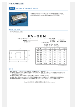
© Copyright 2024