
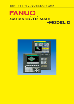
信頼性、コストパフォーマンスに優れたCNC
信頼性、コストパフォーマンスに優れたCNC
High reliable and high cost-performance CNC
信頼性、コストパフォーマンスに優れたCNC
High reliable and high cost-performance CNC
優れた制御機能
CNC機能をパッケージ化
● 優れた研削盤用機能/パンチプレス機能
● 最新のデジタルサーボ技術
(サーボ・スピンドルHRV3制御に標準対応)
●
i
i
FANUC Series 0 / FANUC Series 0
i
High performance
Packages of the most efficient CNC
features
● Distinguished control function
for grinding/punch press machine
● Advanced digital servo technology
(HRV3 control prepared as standard)
●
Mate は、信頼性、コストパフォーマンスに優れたCNCです。
FANUC Series 0 / FANUC Series 0
i
Mate are the high reliable and high cost-performance CNCs.
容易な操作
オペレータに易しい操作
● 簡単操作の加工プログラム作成支援機能
●
充実した保守
高信頼性CNC
● 充実した保守体制
●
最大制御軸 4軸 up to 4 axes
メモリカード
Memory card
表示器と一体のCNC制御部
Control unit incorporated
display unit
先端の機能を提供する構成
より高い機能・生産性を必要とする機械に対応する性能重視
の構成です。
Ease of operation
User friendly operation
● Simple operation programming
support tool
●
Excellence on service & support
●
●
High reliable CNC
Excellence on worldwide service network
series
spindle motor
Configuration with enhanced functions
Performance-oriented configuration for machines that
require improved functionality and productivity
series
amplifier
series
servo motor
i
β シリーズとも接続できます。
Connection can also be
established with a β series.
i
最大制御軸 3軸 up to 3 axes
メモリカード
Memory card
表示器と一体のCNC制御部
Control unit incorporated
display unit
抜群の性能/価格比を提供する構成
基本仕様で性能/価格比重視の構成です。
series
spindle motor
Configuration with excellent cost-performance ratio
Cost-performance ratio-oriented configuration based on the basic
specifications
series
amplifier
series
servo motor
2
3
先進のハードウェア技術
Advanced Technology on Hardware
超小型・省配線
Ultra-Compact CNC with Simplified Cables
液晶表示器裏にCNC制御部を一体化し、
超小型化・超薄型を実現しました。
超高速シリアル通信機能を採用し、
配線ケーブルの本数を大幅に削減しました。
操作部 Operation unit
Ultra-compact CNC is realized through LCD display with integrated CNC.
A few number cables are provided for ultra high-speed serial communication.
強電盤部
Power magnetics cabinet
CNC
サーボモータ
Servo motor
●
FANUC SERVO MOTOR SYSTEM
αiシリーズは、工作機械の高速・高精度化とコンパクト化を
推進する、高速・高精度・高効率のインテリジェントサーボシス
●
αi series is a high speed, high precision and high
efficiency servo system to make machine tools high
speed, precise and compact.
FANUC Serial Servo Bus (FSSB)
●
光ファイバケーブル Optical fiber cable
機能を持っています。
FANUCシリアルサーボバス FSSB
FANUC Serial Servo Bus (FSSB)
CNC制御部と複数のサーボアンプ間を光ファイバケーブルで接続
する高速のシリアルバスです。
The high-speed serial bus with optical fiber cable to connect
servo amplifiers with a CNC control unit.
βiシリーズは、信頼性とコストパフォーマンスに優れたサー
ボシステムです。工作機械の送り軸、主軸用として十分な性能、
●
サーボアンプ
βi series is highly reliable and high cost-performance AC
servo system. This servo system has performance and
functions enough for feed axis and spindle axis of
machine tools.
Servo amplifier
スピンドルモータ
強電盤用I/Oモジュール
Spindle motor
I/O module mounted for
power magnetics cabinet
高信頼性ハードウェア
High reliable Hardware
FANUC I/O Link
ファナックでは、部品メーカ殿と協力して、過酷なFA環境に耐え
る信頼性の高い部品を開発し、加えて、厳しい評価試験に合格し
高速データ転送が可能なFANUC I/O Link
FANUC I/O Link capable of
high-speed data transfer
超小型、超薄型CNC
Ultra Compact , Ultra Thin CNC
FANUC
I/O
Linkは各種のI/OをPMCにシリアルに接続するための
I/Oネットワークで、
モジュール構成のFANUC I/O Unit-MODEL A、
CNC機能を集約した小型プリント板を、液晶表示器と一体化し、
コンパクトな操作盤I/Oモジュール、分線盤との接続ケーブルが不
奥行き70mm(拡張スロット無しの場合)という非常に薄いCNC制
要な分線盤I/Oモジュール等が接続できます。最大1024点のDIと最
御部を実現しました。
大1024点のDOを接続して、
PMCから制御することが可能です。
The small-size CNC integrated with the LCD display realizes
the quite thin CNC control unit in depth of 70mm (in case of
no external slot).
The FANUC I/O Link is an I/O network used to establish a
serial I/O connection of PMC with various I/O devices. Such as
compact operator’s panel I/O module, connection panel I/O
module which does not require the connection cable with the
connection panel and modular type FANUC I/O Unit-MODEL
A. Up to 1024 DI points and up to 1024 DO points can be
connected and used for control from the PMC.
強力な内蔵PMC
Powerful built-in PMC
機械のシーケンス制御や周辺機器用に高速で大容量のPMCを内
蔵しております。
The powerful built-in PMC is available, which executes
sequence control for machine tool and peripheral devices.
● PMC-SA1 5,000steps
● PMC-SB7 24,000steps (0i のみ 0i only)
4
た部品だけを採用しています。また、パートプログラム、パラメ
ータやアプリケーション用メモリなどには、ECC( エラーコレク
I/O Linkβiアンプ
I/O Link βi amplifier
ションコード)を使用する等、積極的に高信頼性技術を取り入れ
サーボモータ
Servo motor
FANUC has developed high reliable components to resist in
the factory environment, jointly with parts suppliers.
Aggressive high quality engineering at FANUC guarantees
quite high reliable CNC perforce with reliability technology
such as memory with error correction code for part
programs, parameters, applications and etc.
周辺軸制御
Additional peripheral axes
I/O Link経由でSERVO MOTOR βi seriesを最大7軸まで拡張できます。
In addition to the CNC controlled axes, maximum 7 units of
SERVO MOTOR βi series are connectable through I/O Link.
5
優れた制御機能
CNC機能をパッケージ化
AI 先行制御
AI 輪郭制御
AI advanced preview control
AI contour control
AI advanced preview control realizes the optimum
acceleration and deceleration of cutting speed by looking
ahead multi-blocks of the part program. This effectively
eliminates machining trajectory error in corners and small
radius, and contributes the high speed and high accuracy
machining.
AI先行制御はプログラムの指令を複数ブロック先読みすることに
より、最適な加減速を実現します。この機能は小さな円弧やコーナ
における加工形状誤差を効果的に除去し、高速高精度な加工を実
現します。
AI輪郭制御は、
より高速高精度な加工を実現することができます。
AI contour control realizes more high speed and high
accuracy machining.
多ブロック先読み補間前加減速
Multiple block look-ahead Acc./dec. before interpolation
接線速度
Tangential
speed
自動コーナ減速
Automatic corner deceleration
N2
加速度による送り速度クランプ
Feedrate clamp by permissible acceleration rate
N1
N6
N2
N1
X
Y
N1
N2
速度
Speed
N1
N2
N3
N4
N5
N6
N7
N3
速度
Speed
N5
N4
N8
N=ブロック番号 block No.
時間
N1
N2, N3, N4, N5
時間 Time
Time
リジッドタップ
Rigid tapping
N6
時間
Time
スケーリング
Scaling
主軸の位置制御を行うことによって、
主軸モータとタップ軸
(Z軸)
が
完全に同期します。
これにより高速高精度なタッピングを実現します。
プログラムで指令された値に対して、0.001∼999.999倍もしくは
0.00001∼9.99999倍の範囲でスケーリングをかけることができます 。
By adopting the position loop in spindle control, the spindle
motor is completely synchronized with the tap axis (Z-axis).
The high speed and high precision tapping is realized.
Program command values can be scaled anywhere in a range
from 0.001 to 999.999 times or from 0.00001 to 9.99999 times.
主軸
Spindle
速度制御
Velocity
control
位置制御
Position
control
位置検出器
Position detector
コレットチャック
Collet chuck
スケーリング後の
移動指令
Move command
after scaling
Z軸
Z axis
スケーリング中心
Scaling center
座標回転
Coordinate system rotation
工具寿命管理
Tool life management
プログラムで指令される形状を回転することができます。
工具をいくつかのグループに分類し、グループ毎の工具の寿命お
よび各グループに属する工具番号をNCのメモリに管理テーブル
の形で設定しておくことができます。
Rotation of a programmed shape is possible.
Y
Tools can be classified into various groups, and the tool life
and the tool numbers for each group can be arranged in the
NC memory in the form of a table.
CCW+
CW−
回転角
Angle of rotation
0
6
入力された移動指令
Move command
X
High performance
Package of the most efficient CNC feature
複合形固定サイクル
Multiple repetitive cycle
円筒補間
Cylindrical interpolation
複合形固定サイクルは簡単な指令で一連の加工経路を作り出します。
例えば加工物の最終形状を定義することにより、
荒加工の工具経路が
自動的に作り出されます。
旋削加工のプログラミングが簡単になります。
The multiple repetitive cycles generate a series of cutting
paths with simple commands. For instance, definition of final
profile of workpiece generates tool path for rough cutting
automatically. It simplifies the lathe programming.
G71 外径/内径
荒削りサイクル
Stock removal
in turning
G73 閉ループ
旋削サイクル
Pattern repeating
円筒の溝切加工に最適です。円筒を展開したとおりにプログラミ
ングできます。
This feature is ideally suitable for cylindrical groove cutting
needs. Programming can be performed precisely as the
cylinder developed.
G76 ねじ切りサイクル
Thread cutting
C 軸
C axis
Z 軸
Z axis
図面寸法直接入力
Direct Drawing Dimension Programming
極座標補間
Polar coordinate interpolation
赤字で記されている直線の角度、
面取りの値、
コーナRの値など図面
上の寸法値を直接に使用することで、
プログラムを簡単にできます。
カム研削や旋盤での正面切欠加工に最適です。加工形状は直交座
標系でプログラミングできます。
The dimension data such as angle of a straight line,
chamfering value, corner radius value, etc., which are
indicated in the red print, can be specified directly as they
are. It simplifies the part programming.
This feature is ideal for cam grinding and face milling (X, C
axis) using a lathe. The machining profile can be
programmed using a cartesian coordinate system.
プログラム例
Sample program
(X2, Z2)
a1
C1
A(a1), C(c1);
X(x3) Z(z3) A(a2) R(r2);
X(x4) Z(z4)
工具の移動(X軸)
Tool movement
(X axis)
(X1, Z1)
r2
(X4, Z4)
ワークの回転
(C軸)
Workpiece
rotation
(C axis)
a2
+Z
(X3, Z3)
+X
カスタムマクロ/マクロエグゼキュータ
Custom macro / Macro executor
ポリゴン加工
Polygonal turning
カスタムマクロとマクロエグゼキュータがMTBによる機械のカ
スタマイズのために用意されています。
ワークと工具を一定の比率で回転させることによって、多角形を
加工できます。
Custom macro and macro executor are available for
customizing machine tool by MTB themselves.
Polygon figure can be machined by rotating the workpiece
and tool at a certain ratio.
工具
Tool
ワーク
Workpiece
六角ボルト
Hexagon bolt
7
優れた制御機能 High performance
CNC機能をパッケージ化 Package of the most efficient CNC feature
パラメータ設定支援画面
Parameter Setting Support Screen
Parameter Setting Support Screen
powerfully supports the necessary
parameter setting for start-up and
adjustment of CNC. In MENU screen,
various setting and adjustment screens
are selected by the cursor operation,
and the parameter is set on each
screen.
パラメータ設定支援画面は、CNCの立上
げと調整のために必要なパラメータの
設定を強力にサポートします。
メニュー画面から、カーソルによって
選択される各項目には、立上や調整に
必要な各種設定をグループ化した、パ
ラメータ設定のためのさまざまな画面
が用意されています。
And, all parameters in group
selected with cursor can be initialized
to the values recommended by
FANUC only by pushing [INIT] Softkey.
また、
ソフトキー
[初期化]
の操作により、
選択された項目の全てのグループのパ
ラメータを、ファナック推奨のデフォ
ルト設定値で初期化することが可能です。
●
立上げのための設定画面
●
Setting screen for start-up
Help screen of the item selected
with cursor in various setting
screens is displayed. And it is
possible to set servo parameters
without complex calculation by
setting machine constant value
directly.
各設定画面では、カーソルで選択され
た項目のヘルプが表示されます。また、
機械定数を直接設定することで、面倒
な計算をすることなく、サーボ設定が
可能です。
●
調整のための設定画面
●
Setting screen for adjustment
The parameter adjustment screens
for the servo and the spindle, and
setting screen of Machining Condition
Selecting Function, are prepared.
サーボモータやスピンドルモータの調
整画面や、加工条件選択機能の設定画
面が用意されています。
記憶形ピッチ誤差補正
Stored Pitch Error Compensation
送りねじのピッチ誤差など、機械系の位置に依存する誤差を補正
します。補正データはパラメータとしてCNCのメモリに記憶さ
せることができます。
With this feature, compensation is carried out for
errorsrelating to mechanical positioning, such as lead screw
pitch error. Compensation data is stored in the CNC memory.
補正量
Compensation value
補正量はCNCのメモリに設定
Compensation value set
in CNC memory
補正原点
Compensation zero point
8
機械位置
Machine
position
勾配補正
Inclination Compensation
送りねじのピッチ誤差など、機械系の位置に依存する誤差を補正
します。その誤差は、パラメータにより設定された補正点と、それ
に対する補正量からできる近似直線に添って補正されます。
With this feature, errors relating to mechanical positioning
such as lead screw pitch error are compensated. The errors
are compensated along 3 approximate straight lines formed
with parameter-specified compensation points and their
compensation amounts.
補正量
Compensation value
機械位置
Machine
position
3本の近似直線に沿って補正
Compensated along 3
approximate straight lines
最新のデジタルサーボ技術 Advanced digital servo technology
αi シリーズアンプ
αi series amplifier
αi シリーズスピンドルモータ
αi series spindle motor
αi
αi
SERVO HRV3 Control
高速・高精度のサーボ制御
極めてなめらかな回転のサーボモ
ー タ 、高 精度の電流検出、高応答・高分
解能のパルスコーダ等のハードウエア
と、サーボHRV3制御の融合で高速・
高精度送りが実現できます。
また、共振追従型のHRVフィルタに
より、周波数の変動する機械共振も回
避可能です。
High speed and high precision servo control
HRV1と比較して約3倍の精度向上
About three times higher precision than HRV1
2μm/div
R26mm
F2m/min
1μm/div
送りの滑らかさ
Smoothness of cutting feed
サーボHRV3の適用例
Application example of SERVO HRV3
スピンドルHRV3制御
SERVO HRV3 control is prepared as
standard.
By combination of
hardware
technology such as “Servo motor
with ultra smooth rotation”,
“Accurate
current detection”,
“High response and high resolution
Pulsecoder”, and ‘SERVO HRV3
Control’, high speed and high
precision feed control can be
realized. And mechanical resonance
can be suppressed by Auto
Following HRV Filter even though
its frequency is changed.
SPINDLE HRV3 Control
高加速・高応答のスピンドル制御
主軸速度 (min-1)
高速DSPと制御ソフトアルゴリズムの
Spindle Speed
85pulse
改善(スピンドルHRV制御)により、電流
制御の応答性と安定性を向上しました。 (HRV1制御と比
較して15%削減)
速度ループ演算周期の短縮と高分解能
(reduced 15%
from HRV1)
検出回路により、高応答・高精度なスピ
ンドル制御を実現しています。
同期誤差 (pulse)
Sync.error
リジッドタップではファイン加減速
(FAD)
とフィードフォワードの併用により、
同期誤差の低減とサイクルタイムの短
1120 ms(HRV1制御と比較して20%減少)
(reduced 20% from HRV1)
縮を図ることができます。
ファイン加減速とフィードフォワードをリジッドタップに適用した場合
Fine Acc & Dec and Feedforward for rigid tapping
サーボガイド
βi シリーズスピンドルモータ
βi series spindle motor
βi シリーズサーボモータ
βi series servo motor
シリーズサーボモータ
series servo motor
サーボHRV3制御
標準でサーボHRV3制御を適用すること
が可能です。
βi シリーズアンプ
βi series amplifier
Quick acceleration and
response spindle control
Quick response and high stability of
current control are much enhanced by
high speed DSP and advanced control
algorithm (SPINDLE HRV Control).
High response and high precision
spindle control is realized with faster
velocity loop sampling time and high
resolution detector circuit.
In rigid tapping with Fine Acc/Dec and
feedforward, reduced synchronous error
and shorter cycle time are expected.
SERVO GUIDE
高速・高精度のサーボ調整を
短時間で実現
Quick & Smart Tuning of
Servo and Spindle
テストプログラム作成、
パラメータ設定、
データ測定などのサーボ・スピンドル
調整に必要な作業を統合的に扱う調整
環境を提供します。共振回避HRVフ
ィルタなどの自動調整にも対応してい
ます。サーボガイドにより、短時間にサ
ーボ・スピンドル関連パラメータの最
適化が行えます。
This
software
provides
the
integrated environment for making
test programs, setting parameters
and data measurement needed for
servo and spindle tuning. It has the
automatic tuning function for
resonance elimination HRV filter
and others. With SERVO GUIDE,
quick and smart optimization of
servo and spindle is realized.
9
優れた制御機能
High performance
優れた研削盤機能 Distinguished control function for grinding machine
円筒研削盤用固定サイクル
Canned cycles for cylindrical grinding
研削加工に特有な繰返し加工を1ブロックで指令することができます。
4種類の研削盤用固定サイクルで、プログラムが容易になります。
Repetitive machining, a function unique to grinding
applications, can be commanded in a block. Four types of
canned cycles are offered to facilitate programming.
ドウェル
Dwell
スキップ信号
Skip signal
傾斜軸制御
Angular axis control
X軸がZ軸に対して90゜以外の角度で取付けられている場合でも、
直交座標系と考えてプログラムすることができます。実際の各軸
の動きは、
自動的に傾斜角度に従って制御されます。
Even in cases where the X-axis is not attached at a 90゜angle
to the Z-axis, programming can be carried out using a
rectangular coordinate system. The actual movements of
each axis are automatically controlled at an oblique angle.
X’
X
スキップ信号
Skip signal
ドウェル
Dwell
トラバース研削サイクル
Traverse grinding cycle
指令プログラム
Command
オシレーション研削サイクル
Oscillation grinding cycle
機械の動き
Machine
movement
θ
多段スキップ
Multi-step skip
Z
定寸寸法測定装置などからのスキップ信号(最大8ヶ)により、実行
中のプログラムをスキップさせることができます。
Using skip signals (max.8) from a measuring instrument or
other device, it is possible to insert skips in a program under
execution.
ワーク外形
Work piece
インフィード制御
Infeed at the swing end point
外部信号を入力するたびに、プログラムした形状に沿って一定量
ずつ切込み制御を行うことができます。
Infeed control can be performed in constant increments along
the programmed figure to allow input of external signals.
テーブル位置決め
Table positioning
荒
Rough
戻り
粗
Return
Coarse
密
スパークアウト
Fine
Spark-out
定寸寸法測定 スキップ1スキップ2スキップ3スキップ4
装置の設定値 Skip1 Skip2 Skip3 Skip4
Settings of
measuring instrument
Y
時間
Time
連続ドレッシングの砥石摩耗補正
Grinding wheel wear compensation in continuous dressing
X
Z
ドレッサ法線方向制御
Dresser control in normal direction
平面研削用固定サイクル中、
連続ドレッシングによるドレス量に応
じて、
砥石の切込み、
およびドレッサの切込みを連続的に補正します。
ドレッサがドレッシング形状に対して常に垂直方向となるように
制御することができます。
This function provides continuous compensation of grinding
wheel cutting and dresser cutting corresponding to the
amount of dressing performed by continuous dressing during
grinding in canned cycles for surface grinding.
The dresser is constantly controlled in a direction vertical to
the dressing figure.
V
Z
Y
X
10
A
優れたパンチプレス機能 Distinguished control function for punch press
最適な加減速制御
Optimum acceleration/deceleration control
位置決め距離に応じて、早送り速度、時定数、ポジションループゲ
インを切り換えることができます。これにより、高速な位置決めと
高ヒットレートを実現します。
Rapid traverse rate, time constant and position loop gain can
be changed according to positioning distance. It realizes high
speed positioning and high hit-rate.
最適なプレス制御
Optimum press control
位置決め距離に応じて、プレス起動信号(PF)の出力タイミングを
調整することができ、
最適なプレス制御を実現します。
Output timing of press start signal (PF) can be adjusted
according to positioning distance, and optimum press control
is realized.
プレス動作
Press
motion
速度
Feedrate
最大速度
Max.Feedrate
D1
D2
プレス動作
Press
motion
ワーク
Workpiece
プレス起動信号(PF)
Press start
signal (PF)
D:距離
Distance
D3
テーブル動作
Table motion
時間
Time
T1
T2
T3
PF 出力タイマー1
PF output timer 1
ニブリング機能
Nibbling function
プレス動作を停止することなく連続的に繰り返してパンチするこ
とができます。Mコードによるニブリングモード、直線ニブリング
(G69)、円弧ニブリング(G68)があります。
Continuous, repetitive punching can be performed without
halting pressing process. Programming can be carried out by
using M command for nibbling mode, linear nibbling (G69)
and circular nibbling (G68).
ニブリングモード(M12, M13)
Nibbling mode (M12, M13)
PF 出力タイマー2
PF output timer 2
パターン機能
Pattern function
1ブロックの指令により、パターンに従った複数個の位置にパン
チを行なわせることができます。8種類のパターン指令があり、プ
ログラムが容易になります。
By giving commands for 1 block, it is possible to perform
punching at multiple positions in a given pattern. Eight types
of pattern commands are offered to facilitate programming.
ボルトホールサークル
Bolt hole circle
♯2
φ
パンチングアーク
Punching arc
♯1
M12 ;
G41 G01 X_ Y_ Q d DΦ ;
G01 X_ Y_ ;
G01 X_ Y_ ;
G03 X_ Y_ I_ J_ ;
G01 X_ Y_ ;
G40 G01 X_ Y_ ;
M13 ;
r
θ
♯n
d
Δθ
r
θ
G26 I r J θK n
C軸制御
C axis control
金型(工具)の角度位置をプログラム指令によって変更することが
でき、工具交換時間が短縮されます。さらに、ボルトホールサーク
ル、アークのパターン機能や円弧ニブリングにおいては、各々の穴
あけ位置で金型の一辺が円弧の中心方向に向くように制御します。
Angular position of a die (tool) can be changed by program
command, and tool changing time is reduced. In addition, in
bolt hole circle, arc pattern and circular nibbling, C axis is
controlled to maintain one edge of the die facing to arc center
at each punching position.
G88 I r J θK Δθ PΦ Q d
セーフティゾーンチェック
Safety zone check
セーフティゾーンチェックにより、プログラムミスや操作ミスに
よる工具とワークホルダの干渉を防止することができます。
Safety zone check prevents interference between tool and
workpiece holder, which keeps away from damage caused by
miss-programming or miss-operation.
パンチ禁止領域では、テーブル移動しないでアラーム停止
In case of punch forbidden area, alarm is displayed without table motion
♯n
工具
Tool
アーク指令
Arc command
♯2
G77 I r J θ P ΔθK n Cθ;
r
工具の方向
Tool direction
Δθ
ワークホルダ
Workpiece holder
次のパンチ位置
Next punch
position
干渉
Interference
♯1
θ
11
容易な操作 Ease of Operation
オペレータに易しい操作 User friendly operation and assistance
グラフィック表示
Graphic display function
プログラムの工具軌跡をCNC画面上にグラフィック表示することができ
ます。
加工の前にグラフィックでプログラム動作を見ることができます。
Tool paths of part programs are able to be drawn graphically
on the CNC display. It offers visual program review prior to
machining.
アラーム履歴・操作履歴
Alarm history and operation history
アラームや操作の履歴が自動的にCNCのメモリに保存され、診断の
ために使用できます。
Alarm and operation status is recorded automatically in the
non-volatile CNC memory and can be used for diagnostics.
メモリカードにより一括待避・復元
Saving and restoring by memory card
サーボ波形表示
Servo waveform display
ポジションエラー、指令パルス、トルク指令などをCNC表示器上に
波形として表示します。オシロスコープ無しにサーボのトラブル
シューティングやチューニングが容易にできます。
Various servo data such as position errors, command pulses,
torque commands, are displayed on CNC display with
waveforms. It facilitates tuning servo conditions and
troubleshooting servo problems without oscilloscope.
ヘルプ機能
Help function
ヘルプ機能は分かり難いアラームの対策と詳細をオペレータに示
します。
Help function will assist an operator for details and
countermeasure of any CNC alarm once lack of familiarity on
CNC operation.
多様な表示器
Variety of display units
液晶ユニット前面に装着されたメモリカードによりパラメータ、
NCプロ
グラム、
オフセットデータ等のCNC内部データを一括待避・復元できます。
LCD表示器は7.2”モノクロ、8.4”カラー、10.4”カラーから選択で
きます。MDI付きのユニットには縦形と横形から選択できます。
CNC data such as parameters, part programs, and offset data,
can be saved to the PCMCIA memory card on the front of the
LCD unit with easy operation, and are also restored
conveniently from it for recovering CNC memory just in case.
LCD units can be selected from 7.2” monochrome LCD, 8.4”
TFT color and 10.4” TFT color. LCD units with MDI can be
selected between vertical type and horizontal type.
縦形
Vertical type
横形
Horizontal
type
PCMCIA
Memory card
12
縦形
Vertical type
横形
Horizontal
type
LCD
MDI
7.2” モノクロLCD /MDI
7.2” monochrome LCD/MDI
8.4” カラーLCD /MDI
8.4” color LCD/MDI
10.4” カラーLCD
10.4” color LCD
汎用旋盤の加工をNCプログラムなしで実現する統合操作ガイダンス機能
Integrated Operation Guidance for NC program-less conventional lathe machining
TURN MATE
ターンメイトiは、NCプログラムなしで、汎用旋盤の加工を実現し
ました。画面に表示された案内図に従って、データを入力すること
により、簡単に旋削加工を行なうことが可能です。操作性を最優先
に考えた以下の画面を準備しました。
●
●
●
TURN MATE i has accomplished NC program-less turning
operation for conventional lathe. It is possible to carry out
turning easily only by following guidance drawings on screen
and inputting data. Following screens, considering operability
as the most important, are prepared.
統合操作画面 ● サイクル入力画面
●
All-in-one screen
●
Cycle input screen
工具選択画面 ● 主軸回転数設定画面
●
Tool select screen
●
Spindle setting screen
●
Feed rate setting screen
送り速度設定画面
タッチパネル
7.2インチモノクロームLCD表示器にタッチパネルを採用しました。
タッ
チパネルにより、
情報の表示と操作を一体化することに成功しました。
画面に表示されている情報をタッチするだけで、
関連する操作画面が呼
び出されます。
また、
運転に必要な情報全てを、
ひとつの画面に統合しま
した。
直感的な操作と見易い画面が、
現場の加工作業を支援します。
豊富なサイクル加工
汎用旋盤に必要なサイクル加工を網羅しています。図面によく現
れる加工形状をパターン化し、形状入力の省力化を図りました。親
切な案内図が、
サイクル加工のデータ入力を支援します。
Touch Panel
Touch panel is applied to 7.2" monochrome LCD unit. Using
touch panel, information and operation are linked
successfully. Only touching information on screen, a related
operation screen appears. And all information for machining
are integrated into one screen. Intuitive operation and plain
screen help your turning work in job shop.
Various canned cycles
All necessary cycles for conventional lathe are covered.
Patterning turning contours which often appear on drawings,
input operation for contours can be saved. User friendly
guidance drawing helps you to input cycle data.
●
荒加工
(パターン形状、任意形状)
●
Roughing
(Pattern figure, Free figure)
●
仕上加工
(パターン形状、任意形状)
●
Finishing
(Pattern figure, Free figure)
●
溝加工
(パターン形状)
●
Grooving
(Pattern figure)
●
Threading
(General thread)
●
Re-threading
(General thread)
●
Drilling
(Drilling, Tapping)
●
ネジ加工
(汎用ネジ)
●
ネジ再加工
(汎用ネジ)
●
穴あけ加工
(ドリル、
タップ)
13
簡単な操作 Ease of Operation
簡単操作に徹した統合操作・プログラミングガイダンス機能
Integrated Operation & Programming Guidance with extremely simplified operations
MANUAL GUIDE
マニュアルガイドiは、加工プログラムの作成から実加工までの全
ての操作を一つの画面上で簡単に操作できる操作ガイダンス機能
です。旋盤およびマシニングセンタ・フライス盤で使用することが
できます。
MANUAL GUIDE i is an integrated operation guidance, which
provides handy operation guidance from programming
through machine operation on one single screen. It can be
applied to lathe, milling machine and machining center.
●
Integrated Operating Screen
●
統合操作画面
●
ISO code part programming
●
ISOコード形式のプログラミング
●
●
強力なプログラム編集操作
●
Powerful Program Editing Functions
Various canned cycles
●
豊富なサイクル加工
●
Set-up Guidance
●
Realistic Machining Simulation
●
段取り支援機能
●
リアルな加工シミュレーション
統合操作画面
必要な操作を一つの画面に集約し、画面を切り替えずにCNCを簡単
に操作できます。
また、
必要に応じて、
ウィンドウが開くことにより、
詳細なデータを表示させることができます。
強力なプログラム編集機能
加工現場でのプログラム編集操作をサポートするために、以下の
ような強力な編集機能が用意されています。
●
切取り
(コピー)
& 貼付け
Integrated Operating Screen
All the necessary operations are concentrated to one single
screen. And, it is possible to operate easily a CNC without
changing a screen. And, if necessary, the window will be
opened in order to display the detailed data.
Powerful Program Editing Functions
In order to support the program editing operations at shop
floor, following powerful editing functions are prepared.
●
Cut, Copy & Paste
●
Guidance Message
●
ガイダンスメッセージ
●
Fixed form program menu
●
定型文入力
●
M-code menu
●
Mコードメニュー
●
Contour Programming
●
輪郭プログラミング
14
リアルな加工シミュレーション
Realistic Machining Simulation
作成したミリング加工、旋削加工のプログラムは、工具軌跡描画あるいはア
ニメーションにより簡単にチェックすることができます。
アニメーションには、
以下の素材形状を指定することができます。
・直方体 ・円筒成形材
・円筒 ・多角柱
Entered program for milling and turning can be checked easily by tool
path drawing or animated drawing.
Following work-piece forms can be used for animated drawing.
・Rectangular
・Preformed cylinder
・Cylinder
・Prism
段取り支援機能
Set-up Guidance
加工の段取り作業において、簡単な画面操作でワークの取付け誤差や工具
補正量、および加工済みワークの計測をメニューから簡単に行うことがで
きます。
In preparation for machining, simple instructions in menu form on a
selected screen enables measuring of work-piece setting error, tool
offset value and machined work-piece.
簡単操作に徹したプログラミングガイダンス機能
Programming Guidance with extremely simplified operations
MANUAL GUIDE
マニュアルガイド0iは、プログラム作成のみに特化し、簡単操作を
追求したプログラミング操作ガイダンス機能です。旋盤およびマ
シニングセンタ・フライス盤で使用することができます。
●
ISOコード形式のプログラム
●
GコードおよびMコードヘルプ機能
●
輪郭プログラミング
●
豊富なサイクル加工
●
ISO code part programming
G-code and M-code assistance
●
Contour programming
●
Various canned cycles
●
ISOコード形式のプログラム
マニュアルガイド0iは、ISOコード形式のプログラムを採用してい
ます。直線や円弧などの簡単な動作はGコードで直接入力し、ポケ
ット加工や穴あけパターンなど複雑な動作は、加工サイクルで簡
単に入力できます。
CNCプログラム画面
CNC program screen
MANUAL GUIDE 0i is a part programming operation
guidance, which is concentrated to the functionality for
creating a part program, and it pursues the extreme simple
operation. It can be applied to lathe, milling machine and
machining center.
ISO code part programming
“MANUAL GUIDE 0i” adopted ISO code program for its part
program language. Simple motion such as line and arc are
entered by G-code directly, and complex motions such as
pocket machining and drilling patterns can be entered easily
by cycle machining blocks.
メニュー画面
Menu screen
穴パターン画面
Hole pattern screen
15
保守・顧客サポート体制
Maintenance and Customer Support
充実した保守体制
ファナックの支社・テクニカルセンタ
ファナックは、弊社商品をお使い頂く限り、責任を持って保守させ
北海道支社
て頂いております。リモートサポート&サービスCS24iを通じて、24
Hokkaido Branch
時間サポートも実施しております。なお、全国各地にサービス拠点
を設け、きめ細かく充実した保守体制を整えております。また、全
世界に広がるサービス拠点もご利用いただけます。
越後テクニカルセンタ
Echigo Technical Center
Worldwide Customer Service and Support
FANUC operates customer service and support network
worldwide through subsidiaries and affiliates. FANUC
provides the highest quality service with the prompt response
at any location nearest you.
北陸テクニカルセンタ
東北テクニカルセンタ
Hokuriku Technical Center
Tohoku Technical Center
前橋テクニカルセンタ
中国テクニカルセンタ
Maebashi Technical Center
Chugoku Technical Center
筑波支社
広島テクニカルセンタ
Tsukuba Branch
Hiroshima Technical Center
日野事業所
Hino Complex
九州支社
Kyushu Branch
Luxembourg
Stuttgart
Prague
Sofia
中央テクニカルセンタ( FA & ROBOT)
Moscow
Central Technical Center
Istanbul
Kimhae
London
Dalian
Paris
Beijing
Barcelona
Shanghai
Shenzhen
Hong Kong
Bangkok
Milan
Chicago
FANUC Headquarters
関西支社
Detroit
Kansai Branch
名古屋セールス支社
Nagoya Sales Branch
Charlottesville
Taipei
Taichung
Manila
Bangalore
Ho Chi Minh
日本国内でのFA商品の保守サービスは、
ファナックFAサービス
(株)
で承っています。
Kuala Lumpur
Singapore
連絡先 〒191-8509 日野市旭が丘3-5-1 TEL 0120-240-716 FAX 0120-240-833
Jakarta
Johannesburg
Sydney
FANUC Training Center
ファナック学校
FANUC Training Center operates versatile
training courses to develop skilled
engineers effectively in several days.
ファナック学校では、CNCを自在に使いこなす
熟練エンジニアを短期間で育成する各種CNCコ
ースを用意しております。
Inquiries : Yamanakako-mura, Yamanashi,
Japan 401-0501
Phone : 81-555-84-6030
Fax : 81-555-84-5540
連絡先 〒401-0501 山梨県山中湖村
TEL(0555)84-6030/FAX5540
本社 〒401-0597 山梨県忍野村 (0555)84-5555(代) FAX
●お問合せ先 下記のFAセールス担当にご相談下さい。
(0555)84-6120 FAX
中央テクニカルセンタ
(0568)73-7821 FAX
名古屋セールス支社
(06)6614-2111 FAX
関西支社
(042)589-8913 FAX
日野事業所
(029)837-1162 FAX
筑波支社
北海道支社
(011)385-5080 FAX
(096)232-2121 FAX
九州支社
(0555)84-6030 FAX
●ファナック学校
北陸テクニカルセンタ
前橋テクニカルセンタ
中国テクニカルセンタ
東北テクニカルセンタ
越後テクニカルセンタ
84-5543
73-5387
6614-2121
589-8899
837-1165
385-5084
232-3334
84-5540
84-5512 http://www.fanuc.co.jp
(0766)56-4421 FAX
(027)251-8431 FAX
(086)292-5362 FAX
(022)378-7756 FAX
(0258)66-1101 FAX
56-4429
251-8330
292-5364
378-7759
66-1141 ●Headquarters Oshino-mura, Yamanashi 401-0597, Japan Phone: 81-555-84-5555 Fax: 81-555-84-5512 http://www.fanuc.co.jp
● America
GE Fanuc Automation Americas, Inc.
FANUC AMERICA CORPORATION
●Europe, the middle east and Africa
GE Fanuc Automation CNC Europe S.A.
FANUC EUROPE SERVICE GmbH
FANUC FRANCE S.A.S.
FANUC U.K. LIMITED
FANUC ITALIA S.p.A.
FANUC IBERIA, S.A.
FANUC TURKEY LTD
FANUC BULGARIA CORPORATION
FANUC CZECH s.r.o.
FANUC SOUTH AFRICA (PROPRIETARY) LIMITED
FANUC MITSUI AUTOMATION CIS LLC
Tel 1-434-978-5000
Tel 1-847-898-5000
Fax 1-434-978-5320
Fax 1-847-898-5001
Tel 352-727979-1
Tel 49-7158-187300
Tel 33-1-4569-6333
Tel 44-1895-634182
Tel 39-02-4887-291
Tel 34-93-664-4820
Tel 90-216-651-1408
Tel 359-2-963-3319
Tel 420-234-072-950
Tel 27-11-392-3610
Tel 7-095-956-9780
Fax 352-727979-214
Fax 49-7158-187411
Fax 33-1-4569-0325
Fax 44-1895-676140
Fax 39-02-4571-3566
Fax 34-93-665-0695
Fax 90-216-651-1405
Fax 359-2-963-2873
Fax 420-234-072-960
Fax 27-11-392-3615
Fax 7-095-956-9785
●本機の外観及び仕様は改良のため予告なく変更することがあります。
●本カタログからの無断転載を禁じます。
● Asia and Oceania
FANUC KOREA CORPORATION
FANUC TAIWAN LIMITED
BEIJING-FANUC Mechatronics CO., LTD.
FANUC INDIA PRIVATE LIMITED
FANUC THAI LIMITED
FANUC MECHATRONICS (MALAYSIA) SDN. BHD.
PT. Fanuc GE Automation Indonesia
FANUC SINGAPORE PTE. LTD.
FANUC OCEANIA PTY. LIMITED
FANUC PHILIPPINES CORPORATION
FANUC VIETNAM LIMITED
FANUC HONG KONG LIMITED
●All specifications are subject to change without notice.
●No part of this catalog may be reproduced in any form.
Tel 82-55-346-0122
Tel 886-4-2359-0522
Tel 86-10-6298-4726
Tel 91-80-2852-0057
Tel 66-2-662-6111
Tel 60-3-7628-0110
Tel 62-21-4584-7285
Tel 65-6-567-8566
Tel 61-2-8822-4600
Tel 63-2-891-3313
Tel 84-8-824-6638
Tel 852-2375-0026
Fax 82-55-346-2548
Fax 886-4-2359-0771
Fax 86-10-6298-4741
Fax 91-80-2852-0051
Fax 66-2-662-6120
Fax 60-3-7628-0220
Fax 62-21-4584-7288
Fax 65-6-566-5937
Fax 61-2-8822-4666
Fax 63-2-891-3315
Fax 84-8-824-6637
Fax 852-2375-0015
F0i C-03, 2005.4, Printed in Japan
© Copyright 2024