
KDF KDF-SB
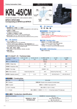
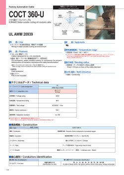
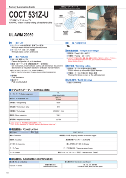
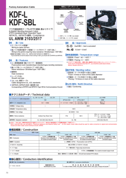
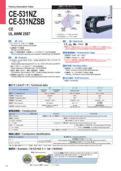
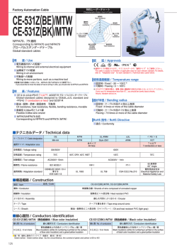
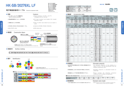
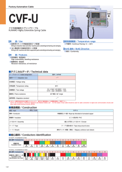
特性レーダーチャート
Factory Automation Cable
Characteristics Rader chart of Cable
KDF
KDF-SB
耐熱性
Heat resistance
5
難燃性
Flame
resistance
4
耐油性
Oil resistance
3
2
1
0
ケーブルベア試験
Cable carrier
resistance
クラモ耐久性ロボット用ケーブル (ETFE 絶縁 )
耐左右屈曲
left/right
bending
resistance
KURAMO Durable Robot Cable (ETFE Insulation)
NFPA70、NFPA79 適用 / Compliance
UL AWM 2103/2517
耐ノイズ性
Noise
resistance
耐捻回性
Twist resistance
KDF(シールド無 / non-shield)
KDF-SB(シールド付 / shield)
用 途 / Use
認 証 / Approvals
■ケーブルベアへの配線
Wiring to cable carriers
■ロボットアーム旋回部分への配線※
Wiring to robot arm turning part
■耐ノイズ性要求箇所への配線(シールド付タイプ:KDF-SB)
Wiring to the portion requiring noise resistance(Shielded type:KDF-SB)
※
※配線方法の詳細につきましては、NFPA70 及び NFPA79 をご参照下さい。
If you would like to know the detail of how to wiring in USA, you should refer to NFPA70 and NFPA79.
使用温度範囲 / Temperature range
■固定時 / Fixed:-40 〜 105℃ ※
■可動時 / Flexing:0 〜 105℃
※ 0℃以下でご使用の際は、衝撃・屈曲・振動等の外的力が加わらないようにしてください。
If you use it in temperature less than 0℃ , you should be careful about shocks,
flexure, vibration and so on.
特 長 / Features
曲げ半径 / Bending radius
■ふっ素樹脂絶縁・耐屈曲性
Fluorocarbon resin insulation, bending resistance
■耐ノイズ性 (シールド付タイプ:KDF-SB)
Noise resistance(Shielded type:KDF-SB)
■耐熱性
Heat resistance
■シースつや消し
Sheath mat type
■ UL・cUL 規格ケーブル
Cable designed to UL, cUL standards
■ NFPA70, NFPA79 対応(通信用 CM)
Corresponding to NFPA70 and NFPA79
(Type CM for Communications Circuits)
■固定時:ケーブル外径の 4 倍以上推奨
Fixed:4 times or more of the cable diameter
■可動時:ケーブル外径の 7.5 倍以上推奨
Flexing:7.5 times or more of the cable diameter
RoHS 指令 / RoHS Directive
■適合 / Conformity
■テクニカルデータ / Technical data
ケーブルタイプ / Cable designation
適用サイズ / Adaptation size
定格電圧 / Voltage rating
UL CM(UL 444)
cUL CM
CM
全サイズ
All Size
UL AWM(UL 758)
STYLE 2517
AWM
1P,2P
3P 以上
3P or more
全サイズ
All Size
−
300V
定格温度 / Temperature rating
105℃
試験電圧 / Test voltage
難燃性 / Flame resistance
適用規格 / Adaptation standard
cULAWM
STYLE 2103
AC2000V・1min
Vertical-Tray Flame Test
UL 444 CSA C22.2 No.214
FT2
VW-1
UL 758
FT2:2P 以下 / 2P or less
FT1:3P 以上 / 3P or more
CSA C22.2 No.210
KDF,KDF-SB は電気用品安全法が適用されませんので、信号及び通信回路などの弱電流回路にご使用下さい。
KDF and KDF-SB are excluded to“Electrical Appliance and Material Safety Law”, for this reason, those cable should be used for cable connection to signal and communication
circuits and other weak current elctrical circuits JAPAN.
69
< 1 〜 25P に適用 / Appliance to 1-25P >
■構造概略 / Construction
品名 / Code
KDF
導体 / Conductor
KDF-SB
0.2㎟
0.3㎟ ,0.5㎟
0.2㎟
0.3㎟ ,0.5㎟
すずめっき軟銅集合線
Strands of wire composed of
tin-coated annealed copper
すずめっき軟銅複合より線
Rope-lay stranded of tincoated annealed copper
すずめっき軟銅集合線
Strands of wire composed of
tin-coated annealed copper
すずめっき軟銅複合より線
Rope-lay stranded of tincoated annealed copper
項目 / Item 絶縁体 / Insulation
ふっ素樹脂(ETFE)/ Fluorocarbon resin (ETFE)
対より / Conductor stranding
線心を対より / Twisted pair
より合わせ / Pair strand
対より線心を円形により合わせ / Strands of twisted pair in circular form
テープ / Tape
テープ重ね巻き / Tape wrap around cores
シールド / Shield
−
シース / Sheath
すずめっき軟銅線編組 / Tin coated annealed copper braid
耐油・耐熱性ビニル混合物(黒色)/ Oil and heat resistant PVC (black)
KDF
KDF-SB
■線心識別 / Conductors identification
対番号 / Pair No.
1
線心番号 / Conductor No.
絶縁体色
Insulaiton Color
2
L1
L2
青
Blue
対番号 / Pair No.
L2
絶縁体色
Insulaiton Color
13
L1
L2
黄
Yellow
灰
Gray
対番号 / Pair No.
絶縁体色
Insulaiton Color
L2
L2
L1
L1
緑
橙
Green Orange
24
L2
L2
赤
Red
赤
Red
灰
Gray
L1
6
L1
L2
紫
橙
Purple Orange
青
Blue
16
L2
白
紫
茶
White Purple Brown
7
L1
L2
L1
L2
青
Blue
灰
Gray
L1
9
L1
茶
黄
黒
緑
Brown Yellow Black Green
17
L1
8
L2
18
L2
L1
L2
L1
灰
Gray
赤
Red
L2
L1
19
L2
L1
黄
橙
緑
白
Yellow Orange Green White
赤
Red
10
L2
L1
11
L2
橙
紫
白
Orange Purple White
20
L1
L2
青
Blue
黒
Black
21
L2
茶
紫
黒
Brown Purple Black
L1
22
L2
青
Blue
L1
L2
橙
黄
白
Orange Yellow White
25
L1
緑
茶
Green Brown
L2
15
L2
赤
Red
5
L1
14
L1
23
線心番号 / Conductor No.
4
L1
白
黄
茶
緑
黒
White Yellow Brown Green Black
12
線心番号 / Conductor No.
3
L1
L1
黒
紫
Black Purple
L2
灰
Gray
■例示 / Example : KDF 8(4P)× 0.3㎟(23AWG)
対より線心
pair conductor
導体/ Conductor
第1種線心(L1)
L1 conductor
L2
第2種線心(L2)
L2 conductor
絶縁体/ Insulation
KDF KURAMO 耐久性ケーブル(耐屈曲 耐熱 耐油型)0.3㎟ LF GOST-R
KURAMO E317214(UL)CM 23AWG 105C or AWM 2517 105C 300V VW-1 …
C(UL)CM 23AWG 105C or AWM I A/B 105C 300V FT1
<<PS
PS>>EE
L1
テープ/ Tape
シース/ Sheath
UL
UL AWM
AWM
■配列図 / Conductors Layout
3P
4P
5P
1
1
2
1
1
1
2
5
4 3
3 2
9 1 2
10 1 2
8
7
9
8
3
4
7 6 5
4
2
3
7
6
1
5 4
2
3
8
7
6
1
5
2
3
4
12P
15P
20P
25P
12 1 2
3
11
4
10
5
9
8 7 6
10 1 2
9 15 11 12 3
8 14 13 4
7 6 5
13 1 2
12 14
3
15
20
11
4
16
19
10 18 17 5
9
6
8 7
16 1 2
15 17
3
18 4
14 25
19 5
13 24
20 6
12 23
11 22 21 7
10 9 8
GOST-R
GOST-R
6 5
3
4
1
8P
CCC
CCC
10P
3
2
6
5
7P
CE
CE
9P
4
6P
cUL/CSA
cUL/CSA
2P
NFPA70
NFPA70
NFPA79
NFPA79
1P
70
KDF , KDF-SB
< 30P に適用 / Appliance to 30P >
■構造概略 / Construction
品名 / Code
KDF
導体 / Conductor
KDF-SB
0.2㎟
0.3㎟ ,0.5㎟
0.2㎟
0.3㎟ ,0.5㎟
すずめっき軟銅集合線
Strands of wire composed of
tin-coated annealed copper
すずめっき軟銅複合より線
Rope-lay stranded of tincoated annealed copper
すずめっき軟銅集合線
Strands of wire composed of
tin-coated annealed copper
すずめっき軟銅複合より線
Rope-lay stranded of tincoated annealed copper
項目 / Item 絶縁体 / Insulation
ふっ素樹脂(ETFE)/ Fluorocarbon resin (ETFE)
対より / Conductor stranding
線心を対より / Twisted pair
ユニット / Unit
5P を円形にユニットより合わせ / Circular (5P) into unit
ユニットより合わせ / Unit stranding
6 ユニットを円形により合わせ / Circular (6 units)
テープ / Tape
テープ重ね巻き / Tape wrap around cores
シールド / Shield
ー
シース / Sheath
すずめっき軟銅線編組 / Tin coated annealed copper braid
耐油・耐熱性ビニル混合物(黒色)/ Oil and heat resistant PVC (black)
■線心識別及び配列図 / Conductors identification and layout
■ 5P 線心識別 / 5P conductors identification
対番号 / Pair No.
線心番号 / Conductor No.
絶縁体色
Insulaiton Color
1
2
L1
L2
青
Blue
L1
3
L2
L1
4
L2
白
黄
茶
緑
黒
White Yellow Brown Green Black
対より線心
pair conductor
5
L1
L2
赤
Red
灰
Gray
L1
L2
紫
橙
Purple Orange
粗巻テープの色
Tape Color
71
第1種線心(L1)
L1 conductor
L2
第2種線心(L2)
L2 conductor
1
2
5
4 3
■ユニット識別 / Unit identification
ユニット番号 / Unit No.
L1
1
2
3
4
5
6
青
Blue
黄
Yellow
緑
Green
赤
Red
紫
Purple
白
White
6
5
1
4
2
3
5Pユニット / 5P Unit
粗巻テープ / Tape
■構造表 / Construction table
導体 / Conductor
外径(約㎜)
公称断面積
外径(約㎜)
Diameter
Nominal cross (Approx.㎜) Diameter
sectional area
(Approx.㎜)
構成
Construction
〈
0.2㎟
<25AWG>
在庫 / Stocks
絶縁 / Insulation
〉
0.6
<40/0.08>
心数
Number of
conductors
1.0
シールド無し / Non-shield
シース外径(約㎜)
概算重量
シールド無 シールド付
Sheath diameter Approx.weight
Non-shield Shield
(Approx.㎜)
(kg/ km)
○
○
3.5
16
4.0
23
○
○
5.7
35
6.2
50
5
3P
○
○
6.2
45
6.7
55
4
4P
○
○
6.4
50
6.9
60
4
5P
○
○
7.2
60
7.7
80
4
6P
○
○
7.7
70
8.2
90
4
7P
○
○
8.0
80
8.5
95
4
8P
○
○
8.8
90
9.3
115
3
9.4
100
9.9
125
3
10P
○
○
10.0
110
10.5
135
3
○
○
11.5
135
12.0
165
3
15P
○
○
11.0
140
11.5
170
3
20P
○
○
12.0
185
12.5
215
2
25P
○
○
1.6
240
14.5
285
2
330
18.5
380
2
○
○
4.1
21
4.6
29
8
2P
○
○
6.8
50
7.3
65
7
3P
○
○
7.3
60
7.8
75
6
4P
○
○
8.1
75
8.4
90
5
5P
○
○
8.7
85
9.2
110
5
6P
○
○
9.5
100
10.0
125
5
7P
○
○
10.0
115
10.5
140
5
8P
○
○
11.0
130
11.0
155
4
11.5
140
12.0
175
4
○
○
12.5
170
13.0
200
4
4
12P
○
○
14.5
215
15.0
260
15P
○
○
14.0
220
14.5
265
4
20P
○
○
15.5
285
16.0
330
3
25P
17.5
355
18.0
410
3
30P
21.5
490
22.5
570
3
40
11
1P
○
○
4.7
28
5.4
2P
○
○
7.9
65
8.2
85
9
3P
○
○
8.9
85
9.4
110
8
4P
○
○
9.8
110
10.5
135
7
5P
○
○
11.0
130
11.5
160
7
6P
○
○
12.0
150
12.5
185
7
○
12.5
175
13.0
210
7
○
13.5
200
14.0
240
6
14.5
230
15.0
270
6
7P
1.1
<3/33/0.08>
14.0
17.5
1P
9P
8P
○
9P
導体抵抗
Conductor
resistance
20℃
(Ω / ㎞)
絶縁抵抗
Insulation
resistance
(M Ω㎞)
6
12P
10P
0.5㎟
<21AWG>
許容電流
Allowable
ampacity
(A)
○
16.0
275
16.5
325
6
○
17.5
320
18.5
375
6
15P
○
○
17.0
335
17.5
395
5
20P
○
○
19.5
445
20.0
495
5
25P
21.5
530
22.0
600
4
30P
28.0
720
28.5
780
4
43.4 以下
1500 以上
(Max 43.4) (Min 1500)
UL
UL AWM
AWM
○
○
71.5 以下
1500 以上
(Max 71.5) (Min 1500)
<<PS
PS>>EE
10P
12P
105 以下
1500 以上
(Max 105) (Min 1500)
KDF
KDF-SB
1.3
シース外径(約㎜)
概算重量
Sheath diameter Approx.weight
(Approx.㎜)
(kg/ km)
2P
30P
0.8
<3/20/0.08>
電気特性 / Electrical characteristics
1P
9P
0.3㎟
<23AWG>
シールド付き / Shield
NFPA70
NFPA70
NFPA79
NFPA79
○は在庫品です。/ ○:Stocks
■許容電流について / Allowable ampacity
cUL/CSA
cUL/CSA
・許容電流値は周囲温度 30℃、空中 1 条敷設時の計算値を示し、保証値ではありません。
Allowable ampacity (A) for cable is based on calculation under aerial one-cable and temperature at 30℃ , not repressenting a guaranteed value.
・周囲温度 30℃以上の場合は、次の電流減少係数を表の値に乗じて下さい。
Allowable ampacity cable at ambient temperature abobe 30℃ is to be determined by multiplying the current value by the appropriate current reduction factorin
the following table1.
CE
CE
・許容電流の値は、JCS0168 により算出した値であって、保証値ではありません。
The allowable ampacity for cable are the calculated by JCS0168, but not guaranteed.
CCC
CCC
JCS0168…日本電線工業会規格“33kV 以下電力ケーブルの許容電流計算”
“Calculation of the current rating of power cables for rated voltage up to and including 33kV”
■表 電流減少係数 / Table1 Current reduction factors
電流減少係数 / Current reduction factors
30
35
40
45
50
55
60
65
70
75
80
85
90
95
100
1.00
0.97
0.93
0.89
0.86
0.82
0.77
0.73
0.68
0.63
0.58
0.52
0.45
0.36
0.26
GOST-R
GOST-R
周囲温度 / Ambient temperature(℃)
72
© Copyright 2024