
カールコード
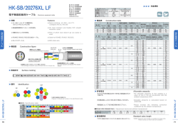
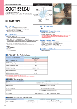
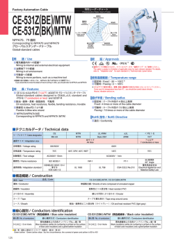
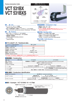
Factory Automation Cable
CVF-U
クラモ高伸縮性スプリングケーブル
KURAMO Highly Extensible Spring Cable
用 途 / Use
使用温度範囲 / Temperature range
■産業用ロボットの伸縮旋回部分への配線
Wiring to industrial robot and other machine parts extending/contracting and swinging
■ NC 機械等の伸縮旋回部分への配線
Wiring to NC machine and other equipment parts extending/contracting and swinging
■可動時 / Continue Flexing:0 〜 60℃
RoHS 指令 / RoHS Directive
■適合 / Conformity
特 長 / Features
■高伸縮性・耐屈曲性
High extensibility, bending resistance
■耐摩耗性・耐油性
Abrasion resistance, oil resistance
■テクニカルデータ / Technical data
ケーブルタイプ / Cable designation
国内 / JAPAN
適用サイズ / Adaptation size
ー※
定格電圧 / Voltage rating
ー
定格温度 / Temperature rating
60℃
0.3 , 0.5㎟:AC1000V・1min
0.75 〜 2㎟:AC3000V・1min
試験電圧 / Test voltage
難燃性 / Flame resistance
60°傾斜 / 60°Angle
ー※
適用規格 / Adaptation standard
※ CVF-U は電気用品安全法が適用されませんので、信号及び通信回路などの弱電流回路にご使用下さい。
CVF-U are excluded to“Electrical Appliance and Material Safety Law”, for this reason, those cable should be used for cable connection to signal and communication circuits and
other weak current elctrical circuits JAPAN.
■構造概略 / Construction
品名 / Code
項目 / Item CVF-U
導体 / Conductor
軟銅複合より線 / Rope-lay Stranded of annealed copper
絶縁体 / Insulation
ビニル混合物 / PVC
より合わせ / Assembly
線心を円形により合わせ / Circular
テープ / Tape
テープを重ね巻き / Tape wrap around cores
シース / Sheath
滑性ウレタン樹脂(黒色)/ Slippery urethane resin (black)
■線心識別 / Conductors identification
12 心以下 / 12 conductors or less
線心番号 / Conductor No.
絶縁体色
Insulaiton Color
1
2
3
4
5
6
7
8
9
10
11
12
黒
black
白
white
赤
red
緑
green
黄
yellow
茶
brown
青
blue
灰
gray
橙
orange
紫
purple
桃
pink
若草
light green
1
2
3
4
5
6
7
8
9
10
11
12
13
14
15
16
黒/白
black
white
赤/白
red
white
緑/白
green
white
黄/白
yellow
white
茶/白
brown
white
黒
black
白
white
赤
red
緑
green
黄
yellow
茶
brown
青
blue
灰
gray
橙
orange
紫
purple
桃
pink
13 心以上 / 13 conductors or more
線心番号 / Conductor No.
絶縁体色 / 識別ライン色
Insulaiton Color
Identification line Color
141
■例示 / Example : 6 心ケーブル / 6 conductors cable
シース / Sheath
絶縁体 / Insulation
導体 / Conductor
● シース外径
Sheath diameter(d)
構造表のとおりです。
As specified in [Construction table]
● スプリング外径
標準は構造表(電線外径の約 3.7 倍)のとおりです。これ以外のものに
ついては、ご相談の上ご指定下さい。
A s gi ven in [C ons tr u c t i on t a b le] (a s s t a n da r d s p e c if i c at i ons
representing approx. 3.7 times the corresponding sheath diameter). If
you need any other optional specifications, contact us for consultation.
● スプリング長さ
標準長は構造表(30, 50, 100, 150, 200㎝)のとおりです。これ以外の
ものについては、10 〜 300㎝の範囲で任意にご指定下さい。
As given in [Construction table] (as standard specifications − 30, 50,
100, 150 and 200㎝ ). If you need any other optional specifications,
specify your requirement in the range of 10 to 300㎝ .
Spring diameter(D)
テープ / Tape
L
ℓ1
ℓ2
D
(L)
Spring length
● 端末長
標準は 30㎝です。これ以外でも任意にご指定下さい。
End length(ℓ 1・ℓ 2) The standard specifications for end length ℓ 1/ℓ 2 are 30㎝ . If
you need any other optional specifications, c ontac t us for
consultation.
● スプリング伸縮量
Spring extensibility
d
標準スプリング外径でスプリング長さの 3 倍以内の伸縮でご使用下さい。
The spring of the cable is designed so that it is extensible up to 3
times the length of the spring when its spring diameter is specified
as standard.
■構造表 / Construction table
導体 / Conductor
絶縁 / Insulation
スプリング仕様 / Spring specifications
シース外径(約㎜)
心数
Sheath diameter
Number of
外径(約㎜)
(Approx.㎜)
公称断面積
外径(約㎜) conductors
Diameter
d
Nominal cross (Approx.㎜) Diameter
sectional area
(Approx.㎜)
構成
Construction
〈
0.3㎟
0.75㎟
1.4
<3/22/0.12>
1.7
<7/16/0.12>
2.6
2.9
3.3
D
概算重量
スプリング 1m 当り
Approx.weight
per 1m of spring
(g)
18
19
20
25
29
34
32
36
22
23
26
31
36
43
41
46
27
29
32
39
49
54
55
61
30
32
35
43
54
59
34
36
40
180
240
290
410
550
720
740
970
290
360
460
650
880
1180
1220
1590
460
590
820
1080
1660
1950
2200
2720
600
750
970
1460
2160
2520
810
1020
1310
4.9
5.1
5.5
6.6
7.7
9.1
8.5
9.6
5.9
6.2
6.9
8.3
9.7
11.7
11.0
12.5
7.3
7.9
8.6
10.5
13.3
14.5
14.9
16.5
8.1
8.5
9.5
11.6
14.6
15.9
9.1
9.6
10.7
30
50
100
○
○
○
○
○
○
○
○
○
○
○
○
○
○
○
○
○
○
○
○
○
○
○
○
○
○
○
○
○
○
○
○
○
○
○
○
○
○
○
○
○
○
○
○
○
○
○
○
○
○
○
○
○
○
○
○
○
○
○
○
○
○
○
○
○
○
○
○
○
○
○
○
○
○
○
○
○
○
○
○
○
○
○
○
150
200
○
○
○
○
○
○
○
○
○
○
○
○
○
○
○
○
○
○
○
○
○
○
許容電流
Allowable
ampacity
(A)
2
2
2
2
1
1
1
1
3
3
3
2
2
2
2
2
4
4
4
3
3
3
2
2
7
7
7
4
4
3
10
10
10
絶縁抵抗
導体抵抗
Insulation
Conductor
resistance
resistance
20℃
(Ω / ㎞) 20℃
(M Ω㎞)
62.3 以下
(Max 62.3)
5 以上
(Min 5)
37.8 以下
(Max 37.8)
5 以上
(Min 5)
25.1 以下
(Max 25.1)
5 以上
(Min 5)
15.1 以下
(Max 15.1)
5 以上
(Min 5)
9.79 以下
(Max 9.79)
5 以上
(Min 5)
NFPA70
NFPA70
NFPA79
NFPA79
2.1
<7/25/0.12>
2.0
スプリング外径
(約㎜)
Spring diameter
(Approx.㎜)
UL
UL AWM
AWM
2㎟
1.2
<3/15/0.12>
1.5
電気特性 / Electrical characteristics
<<PS
PS>>EE
1.25㎟
0.9
<3/20/0.08>
2
3
4
6
8
10
12
16
2
3
4
6
8
10
12
16
2
3
4
6
8
10
12
16
2
3
4
6
8
10
2
3
4
L
(在庫 / Stocks)
CVF-U
0.5㎟
〉
スプリング長さ(約㎝)
Spring length (Approx.㎝)
○は在庫品です。/ ○:Stocks
cUL/CSA
cUL/CSA
● 上記以外の線心数・サイズも製作致します。また、その他用途に応じ各種スプリングケーブルがありますので、ご相談下さい。
CVF-U cable designed to other specifications than as specified in the above table in terms of“number of conductors”and“size”are available. If you need CVF-U spring cable
designed to your application requirements, contact us for consultation.
■許容電流について / Allowable ampacity
CE
CE
・許容電流値は、周囲温度 30℃、空中一条敷設時の計算値を示し、保証値ではありません。
Allowable ampacity (A) for cable is based on calculation under aerial one-cable and temperature at 30℃ , not repressenting a guaranteed value.
・周囲温度 30℃以上の場合には、下表の電流減少係数を許容電流値に乗じて下さい。
Allowable ampacity cable at ambient temperature abobe 30℃ is to be determined by multiplying the current value by the appropriate current reduction factor in the following table1.
・許容電流の値は、JCS0168 により算出した値であって、保証値ではありません。
The allowable ampacity for cable are the calculated by JCS0168, but not guaranteed.
CCC
CCC
GOST-R
GOST-R
JCS0168…日本電線工業会規格“33kV 以下電力ケーブルの許容電流計算”
“Calculation of the current rating of power cables for rated voltage up to and including 33kV”
■表 電流減少係数 / Table1 Current reduction factors
周囲温度 / Ambient temperature(℃)
電流減少係数 / Current reduction factors
30
35
40
45
50
55
1.00
0.91
0.82
0.71
0.58
0.41
142
© Copyright 2024