
3 回転で薄型、微調整タイプ 3 回転型サーフェイス
ST-7
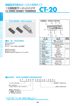
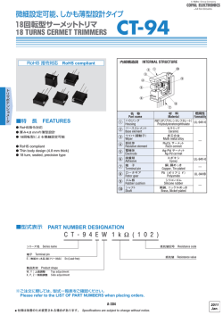
内部構造図
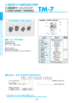
RoHS 指令対応 RoHS compliant
INTERNAL STRUCTURE 1
トリマ
高周波対応
ポテンショメータ
デバイス
3 回転で薄型、微調整タイプ
3 回転型サーフェイスマウントトリマ
Surface mount cermet trimmers (3 TURNS)
!3
!2
8
9
!1
名 称
Part name
● RoHS compliant
● Fine adjustment is possible
● Automatic mounting is possible (Taping)
● Flow/reflow soldering is possible
● Sealed construction (Washable: Refer to page 754.)
1
ロータギア
2
ベースエレメント
3
端 子
4
抵抗体
RuO2 サーメット
5
電極体
Ag-Pd サーメット
6
ハウジングベース
7
ワイパ
(摺動子)
8
シャフト
9
ハウジング
!0
シャフト O リング
!1
Rotor gear
セラミック
Base element
Terminal pin
Ceramic
銅合金、錫‐銅めっき
Copper alloy, Sn-Cu-plated
Resistive element
Electrode
Housing base
Housing
Ag-Pd cermet
PPS(ポリフェニレンサルファイド)
UL94V-0
Polyphenylenesulphide
多元合金
Multi metal alloy
クラッチバネ
!3
固定バンド
—
PPS(ポリフェニレンサルファイド)
UL94V-0
Polyphenylenesulphide
Shaft “O” ring
ベース O リング
Base “O” ring
!2
—
シリコンゴム
UL94HB
ステンレス
—
Silicone rubber
Clutch spring
Stainless steel
Cover
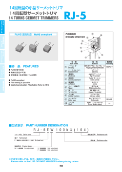
■型式表示 PART NUMBER DESIGNATION
S T - 7 E T A 1 k Ω ( 1 0 2 )
シリーズ名 Series name
抵抗値記号 Resistance code
端子 Terminal pin
抵抗値 Resistance value
E:無鉛めっき品(鉛フリー対応)
Sn-Cu (Lead-free)
包装形態 Form of packaging
T:テーピング(リール)
空欄 Blank:ポリ袋
製品形状
(端子形状)
Product shape (Shape of terminal)
Taping (Reel)
Bulk in plastic bag
A:J - リード
B:ガル・ウィング
※ご注文に際しては、型式一覧表をご確認ください。
Please refer to the LIST OF PART NUMBERS when placing orders.
677
L
E
D
RuO2 cermet
Wiper
Shaft
燃焼性
J-hook
Gull wing
過電流保護素子
● RoHS 指令対応
● 微細な調整が可能
● 自動搭載対応が可能(テーピング)
● はんだフロー / リフローによるはんだ付け可能
● 密閉構造(洗浄可能:754 ページ参照)
材 料
Material
Flammability
PPS(ポリフェニレンサルファイド) UL94V-0
Polyphenylenesulphide
白色 ド ラ イバー
■特 長 FEATURES
4
7 6 5 2
デジタル
ポテンショメータ
!0
3
ST-7
トリマ
高周波対応
ポテンショメータ
デバイス
SURFACE MOUNT TRIMMERS
■型式一覧表 LIST OF PART NUMBERS 〈公称抵抗値〉
調整方向
Adjustment
position
上面調整
Top adjustment
デジタル
ポテンショメータ
白色 ド ラ イバー
L
E
D
<Nominal resistance values>
包装形態 Form of packaging
製品形状
(端子形状)
50 Ω100 Ω200 Ω500 Ω
1 kΩ
2 kΩ
5 kΩ
テーピング(リール)Taping (reel)
ポリ袋 Plastic bag
ST-7ETA
ST-7EA
※ ご注文に際しては、
〈公称抵抗値〉
(Fig. 1)
について上記すべての組み合せを用意
ウィング ) ST-7ETB
B ( ガル・
Gull wing
ST-7EB
※ ご注文に際しては、上記型式をご確認ください。
※ テーピング仕様は、
切り売り致しませんので、
リール単位でご注文をお願い致します。
50 pcs./pack
※ The above part numbers are all available with the respective combination of
<Nominal resistance values> (Fig. 1).
※ Verify the above part numbers when placing orders.
※ Taping specification is not sold separately and must be purchased in reel units.
Shape of terminal
リード
A ( J-J-hook
包装数量
Pieces in package
)
500 pcs./reel
10 kΩ 20 kΩ 50 kΩ 100 kΩ 200 kΩ 500 kΩ 1 MΩ
しています。
■電気的特性
■機械的特性
ELECTRICAL CHARACTERISTICS
公称抵抗値範囲
MECHANICAL CHARACTERISTICS
調整ネジ回転数
50 Ω ~ 1 MΩ
Nominal resistance range
抵抗値許容差
直線性(B)
最大入力電圧
DC200 V 又は定格電力の何れか小さい方
Resistance law
Maximum input voltage
最大ワイパ電流
Maximum wiper current
操作部の押し強さ
固着性
使用温度範囲
−55 ~ 125 °C
抵抗温度係数
50 Ω : ± 250 10-6/°C maximum
100 Ω ~ 1 MΩ : ± 100 10-6/°C maximum
Temp. coefficient
耐基板曲げ性
幅 90 mm たわみ量 3 mm 5 s, 1 回
引きはがし強さ
5 N {0.51 kgf} 10 s
Substrate bending
Width 90 mm, bend 3 mm, 5 s, 1 time
Pull-off strength
1 % or 2 Ω, whichever is greater
{ }:参考値 Reference only
1 % or 3 Ω, whichever is greater
Operating temp. range
5 N {0.51 kgf} 10 s
Shear (Adhesion)
2.5 turns
1 % 又は 3 Ω の何れか大きい方以下
245 ± 3 °C, 2 ~ 3 s
Solderability
100 mA or power rating, whichever is smaller
接触抵抗変化
5 N {0.51 kgf} minimum
Thrust to shaft
はんだ付け性
1 % 又は 2 Ω の何れか大きい方以下
100 cycles [ΔR/R ≦ ± (2 Ω +3 %)]
Rotational life
DC200 V or power rating, whichever is smaller
残留抵抗値
C.R.V.
クラッチ動作 Clutch action
回転寿命
100 mA 又は定格電力の何れか小さい方
Effective electrical turn
End resistance
5 mN·m {51 gf·cm} maximum
回転止
Mechanical stop
Linear law
有効電気的回転数
■環境特性
ENVIRONMENTAL CHARACTERISTICS
試験項目
Test item
試験条件
Specifications
[ΔR/R ≦ 2 %]
[S.S. ≦ 1 %]
1000 MΩ minimum (DC500 V)
熱衝撃
−65 ~ 125 °C (0.5 h), 5 cycles
絶縁耐圧
AC600 V, 60 s
耐湿性
−10 ~ 65 °C ( 相対湿度 80 ~ 98 %),
10 cycles, 240 h
981 m/s2, 6 ms
6 directions for 3 times each
Insulation resistance
Dielectric strength
質 量
Thermal shock
Humidity
耐衝撃性
Approx. 0.25 g
Net weight
Shock
耐振動性
Vibration
〈はんだ耐熱性評価用リフロープロファイル
負荷寿命
Reflow profile for soldering heat evaluation〉
(°C)
250
Peak : 250
+5
0
Load life
低温動作
Low temp. operation
°C
高温放置
High temp. exposure
Over 230 °C
200
150
100
50
180 °C
150 °C
耐水、密閉性
Pre Heating Zone
Immersion seal
仕 様
Test conditions
絶縁抵抗
Temperature
過電流保護素子
抵抗変化特性
回転トルク
Operating torque
0.25 W (70 °C) 0 W (125 °C)
Power ratings
3 turns
Mechanical turn
± 20 %
Resistance tolerance
定格電力
Fig. 1
振幅 (Amplitude) 1.52 mm or
加速度 (Acceleration) 196 m/s2,
[ΔR/R ≦ 2 %]
[ΔR/R ≦ 1 %]
[S.S. ≦ 1 %]
10 ~ 2000 Hz, 3 directions, 12 times each
70 °C, 0.25 W, 1000 h
−55 °C, 2 h
125 °C, 250 h
85 °C, 60 s
[ΔR/R ≦ 3 %]
[S.S. ≦ 1 %]
[ΔR/R ≦ 2 %]
[S.S. ≦ 2 %]
[ΔR/R ≦ 3 %]
[S.S. ≦ 2 %]
もれ無し(連続気泡無し)
No leaks (No continuous bubbles)
フロー:260 ± 3 ℃の槽内に端子先端から
基板の裏面まで 5 〜 6 秒間浸漬を2 回
90 ± 30 s
はんだ耐熱性
30 ± 10 s
Heating time
Soldering heat
Soldering Zone
リフロー回数:2回 Reflow : two times maximum
リフロー:ピーク温度 255℃
(詳細は左記プロファイル参照)
Flow : 260 ± 3 °C as the temperature in a pot of
molten solder, immersion from head of terminal to
backside of board, 5 ~ 6 s, two times maximum
Reflow : Peak temperature 255 °C
(Please refer to the profile below.)
手はんだ Manual soldering:350 ± 10 °C, 3 ~ 4 s
[ΔR/R ≦ 1 %]
Δ R/R:全抵抗値変化 Change in total resistance
Setting stability
S.S. :設定安定度
678
ST-7
■推奨ランドパターン
■最大入力定格
RECOMMENDED P.C.B. PAD OUTLINE DIMENSIONS
MAXIMUM INPUT RATINGS
70.7
50.0
35.4
22.4
1 k
2 k
5 k
10 k
20 k
50 k
102
202
502
103
203
503
15.8
22.4
35.4
50.0
70.7
112
15.8
11.2
7.07
5.00
3.54
2.24
100 k
200 k
500 k
1 M
104
204
504
105
158
200
200
200
1.58
1.00
0.40
0.20
0
0
5.5
3.53
5.00
7.07
11.2
1.6
1.6
1.6
2.35
白色 ド ラ イバー
500
101
201
501
2
デジタル
ポテンショメータ
50
100
200
500
(Unit: mm)
● ST-7EB
2
Maximum wiper
current (mA)
2
Nominal resistance Resistance code Maximum input
values (Ω)
voltage (V)
● ST-7EA
2
最大ワイパ電流
2
最大入力電圧
3.5
抵抗値記号
2
公称抵抗値
トリマ
高周波対応
ポテンショメータ
デバイス
SURFACE MOUNT TRIMMERS
L
E
D
1.6
2.35
注)0 点は搭載中心とする
■外形寸法図 OUTLINE DIMENSIONS
Unless otherwise specified, tolerance : ± 0.3 (Unit : mm)
● ST-7EA
上面調整 Top adjustment
1
0.5 W × 1.8 L × 0.5 D
6.4
1.2
2
1
2 – 0.8
0.02 min.
t = 0.15
3
4.3
6.1
0
6.8 –0.5
1.5
鉛フリー識別記号
Lead-free Identification mark
3.4
1.5
2
3
右回り
CW rotation
2.3
抵抗値及び製造年月記号
Resistance code & Production date code
上面調整 Top adjustment
0.5 W × 1.8 L × 0.5 D
6.4
2
3.4
1.5
1.2
1
7.8
t = 0.15
3
0.02 min.
抵抗値及び製造年月記号
Resistance code & Production date code
0.35 min.
6.1
1.5
鉛フリー識別記号
Lead-free Identification mark
0.35 min.
● ST-7EB
2 – 0.8
2.3
※ The ST-7 series has a different terminal arrange-
※ST- 7シリーズは、ST- 32、4シリーズとは端子
配列が異なり、1番端子と3番端子の位置にご注
意願います。
(R 1〜2間でシャフトをCCWに回
転させると、抵抗値が小さくなります。
)
ment from the ST-32 and ST-4 series. Pay attention
to the location of terminals number 1 and 3.
(Resistance decreases when the shaft is turned
CCW.)
679
過電流保護素子
Note) The zero point is the center of mounting.
ST-7
■ PACKAGING SPECIFICATIONS
■包装仕様
<Taping packaging specifications>
〈テーピングの包装仕様〉
● Taping version is packaged in 500 pcs. per reel.
Orders will be accepted for units of 500 pcs., i.e., 500,
1000, 1500 pcs., etc.
● Taping version is boxed with one reel (500 pcs.).
● テーピングは 500 個 / リール単位の包装になりますので、
500 個単位(500 個、1000 個、1500 個…)
でのご注文をお願
い致します。
箱に包装致します。
製品の脱落は、連続 2 個以内と致します。
Maximum number of consecutive missing pieces = 2
Leader length and reel dimension are shown in the diagrams below.
テープのリーダ部、空部およびリール寸法は図に示します。
ST-7TB Taping
(Unit: mm)
空部
製品装着部
Filled
Empty
17.4±1
終り
21±0.8
始め
End
2±0.5
Head
40 mm min.
20 pitches min.
リーダ部 Leader
引き出し方向
13±0.2
400 mm min.
Direction of feed
254±2
21.4±1
● ST-7ETB
引き出し方向
0.4±0.1
装着例 (ST-7EA)
Installation example
(ST-7EA)
12±0.1
4±0.1
2±0.1
5
0.4±0.1
装着例 (ST-7EB)
Installation example
(ST-7EB)
16
2±0.1
+0.1
0
4±0.1
φ1.5
+0.1
0
φ1.5
12±0.1
1.75±0.1
● ST-7ETA
7.5±0.1
過電流保護素子
Empty
(EIAJ ET-7200A に準拠 In accordance with EIAJ ET-7200A)
50 min.
空部
(JIS C 0806-3 に一致 Conforms to JIS C 0806-3)
7.5±0.1
白色 ド ラ イバー
● リールの寸法図 REEL DIMENSIONS
● テープのリーダ部および空部
EMBOSSED TAPE DIMENSIONS
16
デジタル
ポテンショメータ
● テーピングリールの箱詰めは、1リール(500 個)
ごとに、リール
1.75±0.1
トリマ
高周波対応
ポテンショメータ
デバイス
L
E
D
SURFACE MOUNT TRIMMERS
引き出し方向
Direction of feed
Direction of feed
5
<Bulk pack packaging specifications>
〈ポリ袋の包装仕様〉
● Unit of bulk in a plastic bag is 50 pcs. per pack.
● Boxing of bulk in a plastic bag is performed with 200
pcs. per box.
● ポリ袋での包装は、50 個 / 袋となります。
● ポリ袋の箱詰めは、200 個を製品箱に包装致します。
680
© Copyright 2024