
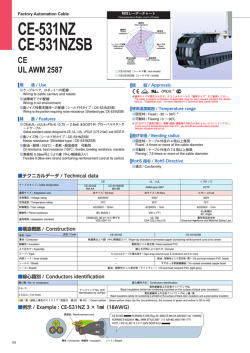
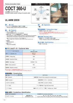
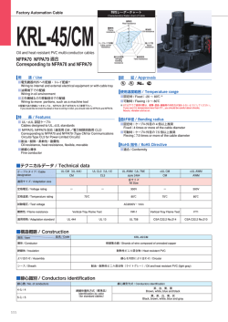
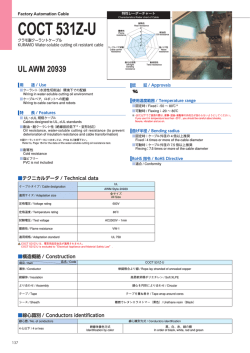
CE-531Z(BE)/MTW
特性レーダーチャート
Factory Automation Cable
CE-531Z(BE)/MTW
CE-531Z(BK)/MTW
Characteristics Rader chart of Cable
耐熱性
Heat resistance
5
難燃性
Flame
resistance
4
耐油性
Oil resistance
3
2
1
0
ケーブルベア試験
Cable carrier
resistance
耐ノイズ性
Noise
resistance
NFPA70、79 適用
Corresponding to NFPA70 and NFPA79
耐左右屈曲
left/right
bending
resistance
グローバルスタンダードケーブル
Global-standard cables
用 途 / Use
耐捻回性
Twist resistance
認 証 / Approvals
■電気機器内外への配線 ※
Wiring to internal and external electrical equipment
■油環境下での配線
Wiring in oil environment
■可動部への配線
Wiring to move portions, such as a machine tool
※
※適用サイズが限定されます。テクニカルデータの“適用サイズ”をご参照ください。
The cable is subject to limitation of applicable sizes for each relevant standard. For details,
refer to “Adaptation size” for each standard in [ Technical data ] given below.
使用温度範囲 / Temperature range
※配線方法の詳細につきましては、NFPA70 及び NFPA79 をご参照下さい。
If you would like to know the detail of how to wiring in USA, you should refer to NFPA70 and NFPA79
■固定時 / Fixed:-30 〜 105℃※
■可動時 / Flexing:0 〜 105℃
※ 0℃以下でご使用の際は、衝撃・屈曲・振動等の外的力が加わらないようにしてください。
If you use it in temperature less than 0℃ , you should be careful about shocks,
flexure, vibration and so on.
特 長 / Features
■ CE & UL・cUL&<PS>E(7 心以下)&GOST-R グローバルスタンダードケーブル
Global-standard cables designed to CE&UL,cUL standard and
<PS>E(7 conductors or less)and GOST-R
■耐油・耐熱・柔軟・耐屈曲性 可動用
Oil resistance, heat resistance, flexible, bending resistance, movable
■素線径 0.08㎜可とうより線
Flexible 0.08㎜ wire strand
■ NFPA70/NFPA79 対応
Corresponding to NFPA70 and NFPA79(MTW)
曲げ半径 / Bending radius
■固定時:ケーブル外径の 4 倍以上推奨
Fixed:4 times or more of the cable diameter
■可動時:ケーブル外径の 7.5 倍以上推奨
Flexing:7.5 times or more of the cable diameter
RoHS 指令 / RoHS Directive
■適合 / Conformity
■テクニカルデータ / Technical data
ケーブルタイプ / Cable designation
CE
MTW
UL AWM
cUL
MA-AA
MTW
Style 2501
AWM
全サイズ
All Size
適用サイズ / Adaptation size
定格電圧 / Voltage rating
定格温度 / Temperature rating
試験電圧 / Test voltage
600V
105℃
90℃ DRY, 60℃ WET
AC2000V・15min
難燃性 / Flame resistance
適用規格 / Adaptation standard
VCT
7 心以下
7 conductors or less
300/500V
70℃
< PS > E
75℃
AC3000V・1min
IEC 60332-1
VW-1
CENELEC HD21.13 に
準ずる
VDE 0281-13
UL 1063
FT-1
UL 758
CSA C22.2 No.210
60 度傾斜
60°Angle
電気用品安全法
Electrical Appliance and
Material Safety Law
■構造概略 / Construction
項目 / Item 品名 / Code
CE-531Z(BE)/MTW, CE-531Z(BK)/MTW
導体 / Conductor
軟銅集合線 / Strands of wire composed of annealed copper
絶縁体 / Insulation
耐熱性ビニル混合物 / Heat resistant PVC
より合わせ / Assembly
線心を円形により合わせ / Circular
テープ / Tape
シース / Sheath
テープを重ね巻き / Tape wrap around cores
耐油・耐熱性ビニル混合物(ライトグレー)/ Oil and heat resistant PVC (light gray)
■線心識別 / Conductors identification
CE-531Z(BE)/MTW(青色絶縁体 / Blue color insulation)
線心数 / No. of conductors
3 心以上 / 3 or more
線心識別方式 / Conductors identification
青色絶縁体上の白色ナンバリング№ + 緑 / 黄
Blue insulations (white ink numbering is printed on the surface
of blue color insulation) and a green/yellow insulation
CE-531Z(BK)/MTW(黒色絶縁体 / Black color insulation)
線心数 / No. of conductors
3 心以上 / 3 or more
●緑 / 黄:緑色と黄色のストライプ(色配分 緑 60:黄 40)
Green/yellow:Green/yellow strips(by the circumference, the covered of green and yellow is 60 to 40)
125
線心識別方式 / Conductors identification
黒色絶縁体上の白色ナンバリング№ + 緑 / 黄
Black insulations (white ink numbering is printed on the surface
of black color insulation) and a green/yellow insulation
■例示 / Example : CE-531Z(BE)/ MTW 8 心ケーブル(7 × 18AWG(0.75㎟)+ 1 × 14AWG(2.5㎟))
2 1
54 3
導体 / Conductor
2.5㎟アース / Grounding conductor
CE-531Z(BE)/MTW
KURAMO-K VDE Reg.-Nr.8369
MA-AA 300/500V
E231466-K(UL)MTW 7/18AWG flexing 1/14AWG flexing 600V or AWM 2501 105C VW-1
… AWM Ⅰ/ Ⅱ A/B 105C 600V FT1
VCT 600V FOR MOVABLE USE LF
テープ / Tape
絶縁体 / Insulation
シース / Sheath
■構造表 / Construction table
CE-531Z(BE)/MTW
電気特性 / Electrical characteristics
導体 / Conductor
絶縁 / Insulation
外径(約㎜)
公称断面積
外径(約㎜)
Diameter
Nominal cross (Approx.㎜) Diameter
sectional area
(Approx.㎜)
構成
Construction
〈
〉
18AWG
1.35
<7/26/0.08>
アース線
Grounding
conductor
14AWG
2.3
<7/71/0.08>
心数
Number of
conductors
在庫
Stocks
8
20
25
41
○
○
○
○
3.05
7
シース外径(約㎜)
Sheath diameter
(Approx.㎜)
概算重量
Approx.weight
(kg/ km)
許容電流
Allowable
ampacity
(A)
310
620
740
1080
5
3
3
2
16.5
22.5
25.0
29.5
22.5
絶縁抵抗
導体抵抗
Insulation
Conductor
resistance
resistance
20℃
(Ω / ㎞) 20℃
(M Ω㎞)
22.8 以下
(Max 22.8)
60 以上
(Min 60)
7.98 以下
(Max 7.98)
45 以上
(Min 45)
770
4.0
○は在庫品です。/ ○:Stocks
●上記の線心数は、14AWG(7/71/0.08)緑 / 黄のアース線 1 心を含んだ線心数です。
The number of conductor of cable, includes a 14AWG(7/71/0.08)green/yellow grounding conductor.
CE-531Z(BK)/MTW
〈
〉
18AWG
1.4
<7/26/0.08>
3.1
16AWG
1.8
<7/43/0.08>
3.5
14AWG
2.3
<7/71/0.08>
4.0
12AWG
2.8
<7/110/0.08>
4.5
10AWG
8AWG
3.6
<7/80/0.12>
4.6
<12/70/0.12>
電気特性 / Electrical characteristics
心数
Number of
conductors
2
3
4
2
3
4
8
2
3
4
8
2
3
4
8
概算重量
Approx.weight
(kg/ km)
許容電流
Allowable
ampacity
(A)
9.7
11.0
11.5
11.0
12.0
13.0
18.0
12.5
13.0
14.0
20.0
13.5
14.5
15.5
22.0
110
135
160
135
165
200
345
160
200
260
495
230
265
370
690
7
7
5
10
10
8
7
20
20
16
14
25
25
20
17.5
シース外径(約㎜)
Sheath diameter
(Approx.㎜)
在庫
Stocks
○
○
○
6.0
4
○
20.0
575
24
7.2
4
○
23.5
800
32
22.5
770
7
アース線
Grounding
conductor
14AWG
2.3
<7/71/0.08>
絶縁抵抗
導体抵抗
Insulation
Conductor
resistance
resistance
20℃
(Ω / ㎞) 20℃
(M Ω㎞)
22.8 以下
(Max 22.8)
60 以上
(Min 60)
13.3 以下
(Max 13.3)
50 以上
(Min 50)
7.98 以下
(Max 7.98)
45 以上
(Min 45)
4.77 以下
(Max 4.77)
40 以上
(Min 40)
3.228 以下
30 以上
(Max 3.228) (Min 30)
2.114 以下
35 以上
(Max 2.114) (Min 35)
7.98 以下
(Max 7.98)
4.0
CE-531Z(BE )/MTW
CE-531Z(BK)/MTW
導体 / Conductor
絶縁 / Insulation
外径(約㎜)
公称断面積
外径(約㎜)
Diameter
Nominal cross (Approx.㎜) Diameter
sectional area
(Approx.㎜)
構成
Construction
45 以上
(Min 45)
<<PS
PS>>EE
○は在庫品です。/ ○:Stocks
● 18,16AWG の線心数は、14AWG(7/71/0.08)緑 / 黄のアース線 1 心を含んだ線心数です。
The number of conductor of 18AWG and 16AWG, includes a 14AWG (7/71/0.08) green/yellow grounding conductor.
CE
CE
CCC
CCC
21-25
26-30
31-35
36-40
41-45
46-50
51-55
56-60
61-70
1.05
1.00
0.94
0.88
0.82
0.75
0.67
0.58
0.33
GOST-R
GOST-R
電流減少係数 / Current reduction factors
cUL/CSA
cUL/CSA
■表 電流減少係数 / Table1 Current reduction factors
周囲温度 / Ambient temperature(℃)
NFPA70
NFPA70
NFPA79
NFPA79
JCS0168…日本電線工業会規格“33kV 以下電力ケーブルの許容電流計算”
“Calculation of the current rating of power cables for rated voltage up to and including 33kV”
UL
UL AWM
AWM
■許容電流について / Allowable ampacity
・許容電流値は周囲温度 30℃、空中 1 条敷設時の計算値を示し、保証値ではありません。
Allowable ampacity (A) for cable is based on calculation under aerial one-cable and temperature at 30℃ , not repressenting a guaranteed value.
・周囲温度 30℃以上の場合は、次の電流減少係数を表の値に乗じて下さい。
Allowable ampacity cable at ambient temperature abobe 30℃ is to be determined by multiplying the current value by the appropriate current reduction factorin
the following table1.
・許容電流の値は、JCS0168 により算出した値であって、保証値ではありません。
The allowable ampacity for cable are the calculated by JCS0168, but not guaranteed.
・欧州では、建物の電気設備の配線システムの許容電流に関しての規格“IEC 60364-5-52(Electrical installations of buildings-Part 5-52:Selection and erection of
electrical equipment - Wiring systems)”がありますのでご参照下さい。
For details on Allowable ampacity of the cable when used in Europe, refer to the applicable standard“IEC 60364-5-52 (Electrical installations of buildings Part 5-52:Selection and erection of electrical equipment - Wiring systems)”
・米国では、米国電気基準産業用機械の電気規定(NFPA79)により、許容電流値及び温度減少係数が定められていますので、ご参照下さい。
For details on Allowable ampacity of the cable and Current reduction factors when used in America, refer to the applicable standard“NFPA79”.
126
© Copyright 2026