
ダウンロードはこちら
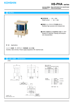
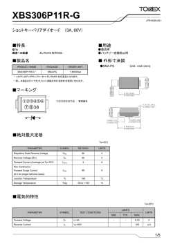
電流センサ関連 CURRENT SENSORS S22P P 1/1 1 1405 磁気平衡式/電圧出力型/ショートリード Servo system / Voltage-output type / Short lead model S22P P SERIES RoHS指令 適合品 仕 様 SPECIFICATIONS Ta=25˚C, RL=10kΩ, Vcc=+5V カタログ品番 Types S22P006S05P S22P015S05P S22P025S05P If 6A 15A 25A If max ±18A ±45A ±75A 項 目 Spec 定格電流 Primary norminal current 飽和電流 Saturation current 定格出力電圧 Rated output voltage Vo Vof±0.625V (at If) 定格出力電圧精度 Output voltage accuracy XG 0.625V±0.010V (at If) オフセット電圧※1 Offset voltage Vof 出力直線性 Output linearity εL ≦±0.2% (at If) 電源電圧 Power supply voltage Vcc +5V±5% 消費電流 Consumption current Icc Typ.12.5mA (If=0A) + 37.5mA (If max) di/dt 応答速度 (@90% of If) Response time 2.5V±0.050V (at If = 0 A) 2.5V±0.020V (at If = 0 A) 2.5V±0.015V (at If = 0 A) tr ≦ 1μs (di/dt = If /μs) 出力電圧温度特性 Thermal drift of gain TCVO ≦ ±0.05mV / ℃ (Without TcVof) オフセット電圧温度特性 Thermal drift of offset TcVof ヒステリシス誤差 Hysteresis error ー10〜25℃:±1.6mV / ℃ 25〜85℃:±0.8mV / ℃ ー10〜25℃:±0.6mV / ℃ 25〜85℃:±0.3mV / ℃ ー10〜25℃:±0.4mV / ℃ 25〜85℃:±0.2mV / ℃ VOH ≦0.5mV(at If = 0A → If → 0A) 絶縁耐圧 Insulation voltage Vd AC3000V, 1分間(感応電流0.5mA) 1次 ⇔ 2次間 AC3000V for 1 minute (Sensing current 0.5mA) Primary ⇔ Sacondary 絶縁抵抗 Insulation resistance RIS ≧500MΩ (at DC500V) 1次 ⇔ 2次間 ≧500MΩ (at DC500V) Primary ⇔ Sacondary 動作温度範囲 Ambient Operating temperature TA ー10℃〜+85℃ 保存温度範囲 Ambient storage temperature TS ー25℃〜+100℃ ※1 オフセット電圧はコアヒステリシス除去後の値とする。 Offset voltage value is after removal of core hysteresis. ※ UL承認条件につきましては、別紙を参照願います。 *Please refer to the another sheet about conditions of UL Recognition. 外形図 DIMENSIONS (mm) 0.8 3-(□0.5×0.25) 注 Note 1. 指示なき寸法公差は±0.5mm Unless otherwise specified, tolerances shall be ±0.5mm 2. 外形寸法の単位はmmとする。 Unit is [mm] 3.5 3.5 0.5 23.5 22.2 端子番号 Terminal number ① IN-1 ② IN-2 ③ IN-3 ④ OUT-3 ⑤ OUT-2 ⑥ OUT-1 ⑦ Vout ⑧ GND ⑨ +Vcc (+5V) 3-0.7 2.54 1.85 7.62 2.54×2=5.08 1 OUT ⑥ ⑤ ④ ⑦ ⑧ ⑨ 3.5 1 2.54 5.08 10 12.7 If/3 If/2 IN IN ① ② ③ IN 17.2 If IN 6 5 4 1 6 2 5 3 4 1 6 2 5 3 4 1 2 3 OUT Tolerance (公差):±0.5 Unit (単位):mm 質量 Weight: 8g typ OUT OUT 電流センサ関連 CURRENT SENSORS Notices 1/1 2 1412 ご注意 Important Notice 1. 本書の記載内容は、改良などにより予告なく変更することがありま す。 ご使用の際には、最新の情報であることをご確認下さい。 2. 本製品は一般的な電子機器(家電製品、事務機器、情報機器、通信 端末機器、計測機器、産業機器など)への使用を意図しております。 極めて高度な品質及び信頼性が要求され、その製品の故障や誤動 作が人命・身体に危害を及ぼす機器、装置(医療機器、輸送機器、 交通信号制御機器、火災・防犯装置、航空宇宙機器、原子力制御、 燃料制御、車載機器、各種安全装置など)の特定用途に使用される ことを目的として設計及び製造されたものではございません。 本資料に個別に記載されている場合を除き、本特定用途に使用され た場合には、お客様または第三者の損害等について当社はいかな る責任も負いかねます。 3. 当社は品質、信頼性の向上に努めておりますが、電流センサはある 程度の確率で機能不具合、故障の発生は避けられません。故障の 結果として、人身事故、火災事故、社会的損傷などを発生させないよ う、使用者の責任において、装置やシステム上での十分な安全設計 と確認を行って下さい。 4. 本書に記載されている動作例および回路例は、使用上の参考として 示したもので、これらに起因する当社もしくは第三者の工業所有権、 知的所有権、その他の権利の侵害問題について、当社は一切責任 を負いかねます。 5. 本書に記載されている回路例、部品定数は、使用上の参考として示 したものです。 使用者の責任において、諸条件を考慮して、設計、 検証、判断を行って下さい。 6. 本製品は一般的な電子機器が設置される環境を意図しております。 下記の例のような特殊環境下での使用を配慮した設計は行っており ませんので、このような特殊環境下で使用される場合は、使用者の 責任において十分な安全性確認と信頼性確認などを行って下さい。 ・水、油、薬液、有機溶剤などの液体中での使用及びこれらが ふりかかる場所での使用 ・直射日光、屋外暴露、塵埃中での使用 ・潮風、Cl2、H2S、NH3、SO2、NO2 などの腐食性ガスのある場 所での使用 (一部製品は耐久性をあげております) ・静電気、電磁波の強い環境での使用 ・本製品に可燃物を配置しての使用 ・本製品を樹脂充填で封止、コーティングしての使用 ・フラックス洗浄で水または水溶性洗剤の使用 ・結露が発生する場所での使用 7. 本製品は耐放射線設計をしておりません。 8. 本書に記載された内容を文章による当社の承諾なしに転記複製を 禁じます。 1. The content of this information is subject to change without prior notice for the purpose of improvements, etc. Ensure that you are in possession of the most up-to-date information when using this product. 2. This product is intended to be used in general electronics applications (electric home appliances, business equipment, information equipment, communication terminal equipment, measuring devices, industrial equipment, and so on). This product is neither intended nor warranted for use in following equipment or devices: Special application (such as for medical devices, transportation equipment, traffic signal control equipment, fire and crime prevention equipment, aeronautics and space devices, nuclear power control, fuel control, in-vehicle equipment, safety devices, and so on) in which extremely high quality and high reliability is required, or if the malfunction or failures of product could be cause loss of human life, bodily injury. Tamura Corporation shall not be held responsible for any damage incurred by customers or any third party when products are used in special application, unless specifically permitted in this document. 3. Tamura Corporation constantly strives to improve quality and reliability, but malfunction or failures are bound to occur with some probability in current sensor. To ensure that failures do not cause accidents resulting in injury or death, fire accidents, social damage, and so on, users are to thoroughly verify the safety of their designs in devices and/or systems. 4. The operation examples and circuit examples shown in this information are for reference purposes only, and Tamura Corporation disclaims all responsibility for any violations of industrial property rights, intellectual property rights and any other rights owned by Tamura Corporation or third parties that these may entail. 5. The circuit examples and part constants listed in these specifications are provided as reference for the verification of characteristics. The user is to perform design, verification, and judgment under his or her own responsibility, taking into account the various conditions. 6. The products are designed for use in environments where consumer electronics are commonly used. It is not designed for use in special environments such as listed below, and if such use is considered, the user is to perform thorough safety and reliability checks under his/her responsibility. Use in liquids such as water, oil, chemical solutions, or organic solvents, and use in locations where the product will be exposed to such liquids.・Use that involves exposure to direct sunlight, outdoor exposure, or dusty conditions. Use in locations where corrosive gases such as sea winds, Cl2, H2S, NH3, SO2, or NO2, are present. (Some product improves durability) Use in environments with strong static electricity or electromagnetic radiation. Use that involves placing inflammable material next to the product. Use of this product either sealed with a resin filling or coated with resin. Use of water or a water soluble detergent for flux cleaning. Use in locations where condensation is liable to occur. 7. This product is not designed to resist radiation. 8. This document and any information herein may not be reproduced without prior written permission from TAMURA. Appli note 電流センサ関連 CURRENT SENSORS 1/1 2 1412 使用上のご注意 Application notes <共通> 1. センサには有極性電子部品が使用されています。接続の際、電源 の極性を誤ると破損します。 2. 静電気、過電圧によってホール素子の不平衡電圧が増加し、オフ セット電圧が変化する場合があります。取扱い及びアプリケーション では充分にご注意ください。 3. ノイズの影響を防ぐため、出力線はツイスト線かシールド線をご使用 することをお奨めします。 4. 他の機器から発生する磁界により、所定の精度が得られない場合 があります。装置内のセンサ配置についてご注意下さい。 5. 弊社製品(一部機種を除く)は、スペックシートの測定条件(負荷条 件 , 入力電圧)にてトリミング調整しております。従って、測定条件と 異なる回路条件下では、各種特性値 ( オフセット、定格出力、etc.) 及びその偏差が変動する可能性があります。尚、スペックシートに は変動する特性項目の全てを記載しているわけではありません。 6. 貫通穴構造の製品は、貫通一次導体の位置により特性(定格出力、 応答性, etc.)が変動します。弊社の特性規定は、製品貫通穴と同面 積の一次導体を使用したときです。 7. スペックシートの定格電流は、設備の都合により直流電流にて規定 しております。 8. コネクタ接続型の製品は、勘合部分の端子メッキが同じものをご使 用下さい。勘合部分のメッキが異金属の場合、ガルバニック腐食に より不具合が発生する可能性があります。 9. 高温高湿の環境下での保存は避けて下さい。6ヶ月以上保管される 場合、はんだ付け性をご確認の上ご使用願います。(基板にはんだ 付けする製品) 10.起動毎にオフセット電圧を基準値として読み込み、ゼロ点調整する ことを推奨します。また、数ヶ月間の連続運転や使用環境の温度/ 湿度の変動が大きいことが想定される製品につきましては、アイドリ ング時(電流が流れていないことが明らかな場合)に定期的なゼロ 点調整を推奨します。 <磁気比例式> 1. 被測定電流の周波数が高い場合には、コア材の鉄損によりコアの 発熱が大きくなり、内部回路が破損する可能性があります。 その場合には、測定電流よりも定格電流が大きい製品を使用される か、磁性体としてフェライト材料を使用している機種を選定して下さ い。 2. 被測定電流が定格電流を超えると鉄芯の飽和により、被測定電流 に比例した出力電圧が得られないことがあります。 <磁気平衡式> 1. 磁気平衡方式製品(Sシリーズ)の両電源製品は、正負の両電源電 圧を同時対称に印加して下さい。同時印加されない場合には、オフ セット誤差が増えます。 2. 最大電流について通電時間制限があります。この時間を超えてご使 用された場合、内部回路が破損する可能性があります。 3. 電流出力タイプに接続する負荷抵抗は、ご希望の出力電圧範囲に あうように精度及び温度特性の良い抵抗をご使用下さい。 4. 2次側電源の消費電流は、被測定電流Ifに比例して増減します(If÷ KN, KN:2次側巻数)。2次側電源の電流能力は十分に持たせて下 さい。 <フラックスゲート方式(磁気平衡型)> 1. 2次側電源の消費電流は、被測定電流に比例して増減します。2次 側電源の電流能力は十分に持たせて下さい。 2. 出力電圧、リファレンス電圧には約450kHzのリップルが含まれており ますので、必要応じて外付けコンデンサを追加して下さい。 <General Considerations> 1. The sensor uses polar electronic components. When the polarity of the power supply is mistaken, the sensor is damaged. 2. Static electricity or excessive voltage can increase an offset voltage in the Hall element, and cause offset voltage to change. Please exercise care in handling and application. 3. In order to prevent the influence of noise, the use of twisted cable or shielded cable for the output line is recommended 4. If using this device within a magnetic field generated by other devices, the specified accuracy may not be obtainable. 5. Our products (several models are excluded ) are adjusted with the trimming method by the measurement condition (Load resistance, Power supply voltage) of specification sheets. Therefore, characteristics (Offset, Output, etc.) and its deviation may be changed in different circuit conditions from the measurement condition. All change characteristic items are not indicated on specification sheets. 6. The performance of current sensors with through-hole (aperture) is dependent on the position of the primary conductor. Tamura specifications are based on a primary conductor completely filling the through-hole (aperture) area. 7. The current sensor rated current in DC Amps. 8. Please use mating connector with equivalent terminal plating material to insure proper operation and avoid possibility of ‘galvanic corrosion’. 9. Please do not store in high-temperature and high-humidity storage environment. Please use it after confirming soldering when it is kept for six months or more. (product soldered with substrate) 10.We recommend performing a zero offset adjustment by measuring the offset voltage at startup. In continuously operation for a few months, or at change of ambient temperature or humidity is large, we recommend regularly performing a zero offset adjustment at being idling (it is clear that the current is not apply). <Open loop> 1. High frequency primary current may result in excessive heating in iron magnetic core and cause damage to internal circuitry; for high frequency applications select current sensor with ferrite core material. 2. If the measured current exceeds the rated current, magnetic core saturation will occur and the output voltage signal will not be linearly proportional to the measured current. <Closed Loop> 1. For closed loop current sensors please insure the power supply voltage is balanced, symmetrical, and, applied simultaneously to avoid potential increase in DC offset error. 2. Maximum rated current measurement duration is timedependent. Maximum rated current applied in excess of the time limit can result in damage to internal electronic circuitry; please consult Tamura for assistance. 3. When using a measurement resistor to convert current output to voltage output select a resistor with stable temperature characteristic to insure accuracy of the output voltage. 4. Compensation current supplied to the secondary winding varies in proportion to the measured current based on the conversion ratio. (If/KN; KN = secondary turns) Please insure the PSU has required current capacity to supply compensation current to the secondary winding. <Flux-Gate> 1. Compensation current supplied to the secondary winding varies in proportion to the measured current. Please insure the PSU has required current capacity to supply compensation current to the secondary winding. 2. There is 450kHz ripple voltage present on the output and reference output voltage signals . An external capacitor maybe added if necessary.
© Copyright 2026