
286 NVF.indd
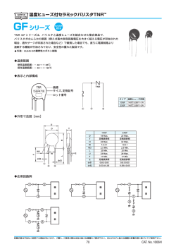
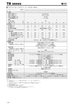
VARISTORS
NVF
NEW
EU
RoHS
金属酸化物バリスタ(不燃型)
Metal Oxide Varistors (Nonflammable Coated)
■構造図 Construction
(mm)
①
D
T
②
③
④
H
L
φ0.8
7.5±1
① 絶縁塗装
② 電極
バリスタ
Varistors
外装色:灰 Body color:Gray
表示:文字表示 Marking:Alphanumeric
Insulation coating
Electrodes
③ バリスタ素子 Varistor element
④ リード線
Lead wire
■寸法 Dimensions
■特長 Features
双方向対称性を有し、正負のサージ吸収が可能です。
● 外装には難燃性シリコーン
(UL94V-0)を採用し
ています。
● 欧州RoHS対応品です。
● Varistors own two-way symmetries and can absorb
positive and negative surges.
● Flame retardant SILICONE (UL94V-0) is
employed for the outer coating.
● Products meet EU-RoHS requirements.
●
寸 法 Dimensions(mm)
形 名
Type
D max.※1
T max.※1
H max.
L
NVF10U
15.0~16.0
6.8~11.5
22.0
3.5±0.5
重 量 Weight(g)
(100pcs)
130~320
※1Dmax.及びtmax.はバリスタ電圧によって変化します。
※1Dmax.andtmax.varyaccordingtothevaristorvoltage.
■用途 Applications
d.c.及びa.c.ラインに接続される機器の誘導雷サージ対策
モータ、リレー等の誘導負荷からのサージ電圧吸収、及び過電圧からの半導体素子の保護。
● Measures for inductive lightning surges of those equipment that are connected to d.c. and a.c. lines.
● Absorption of surge voltages from inductive load of motors, relays, etc.and protection of semiconductor elements from excessive voltages.
●
●
■品名構成 Type Designation
例 Example
NVF
10
U
C
D
F
470
品種
Product
Code
ディスク径
Diameter
of Element
シリーズ
Series
端子表面材質
Terminal
Surface Material
内部接合はんだ
Inner Connect
Solder Material
二次加工 包装
Forming & Packaging
バリスタ電圧
Varistor
Voltage
C:SnCu
D:SnAgCu
F:L=3.5mm バルク
Bulk
Ex.
470V:470
10:φ10mm
U:Uシリーズ
Userise
環境負荷物質含有についてEU-RoHS以外の物質に対するご要求がある場合にはお問合せください。
Contact us when you have control request for environmental hazardous material other than the substance specified by EU-RoHS.
■定格 Ratings
動作温度範囲 OperatingTemp.Range:−40℃~+85℃ 保存温度範囲 StorageTemp.Range:−40℃~+125℃
形 名
Type
NVF10UCDF220
NVF10UCDF240
NVF10UCDF270
NVF10UCDF430
NVF10UCDF470
NVF10UCDF510
NVF10UCDF620
NVF10UCDF680
バリスタ電圧
Varistor
Vol.
(V)
198~242
216~264
247~303
387~473
423~517
459~561
558~682
612~748
最大許容回路電圧
Max. Allowable
Circuit Vol.(V)
a.c.r.m.s. (V)
d.c. (V)
140
180
150
200
175
225
275
350
300
385
320
410
385
505
420
560
エネルギー耐量
Max. Energy
E
(J) T=2ms
27.5
30.0
35.0
55.0
60.0
67.0
67.0
67.0
サージ耐量
Max. Peak Current T=8/20μs
Ip (1 time) (A)
3500
Ip (10000 times) (A)
150
本カタログに掲載の仕様は予告なく変更する場合があります。ご注文およびご使用前に納入仕様書で内容をご確認ください。
車載機器、医療機器、航空機器など人命に関わったり、あるいは甚大な損害を引き起こす可能性のある機器へのご使用を検討される場合には、必ず事前にご相談ください。
Specificationsgivenhereinmaybechangedatanytimewithoutpriornotice.Pleaseconfirmtechnicalspecificationsbeforeyouorderand/oruse.
Contactoursalesrepresentativesbeforeyouuseourproductsforapplicationsincludingautomotives,medicalequipmentandaerospaceequipment.
Malfunctionorfailureoftheproductsinsuchapplicationsmaycauselossofhumanlifeorseriousdamage.
制限電圧
Clamping Vol.
V25A
360
395
455
710
775
845
1025
1120
Oct.2014
www.koanet.co.jp
■取得規格及び範囲 Approval Awarded and Coverage
L1449 (File No. E328032)
U
c-UL1449 (File No. E328032)
●
VDE (IEC61051 IEC60950-1AnnexQ: File No. 40037531)
●
●
■性能 Performance
規格値
Performance Requirements
試験項目
Test Items
試験方法
Test Methods
ΔV±%
規定の許容差内
Within specified tolerance
規定された電流Ic=1mAをバリスタに流した時の端子間電圧
The voltage between terminals when the specified current is flowed.
はんだ耐熱性
Resistance to soldering heat
±5% 外観に異常のないこと
No abnormality in appearance.
260±5℃, 10±1s
はんだ付け性
Solderability
95%以上新しいはんだで覆われていること
95% Coverage min.
230±5℃ 5±0.5s/250±5℃ 5±0.5s
(Pb free)
温度急変
Rapid change of temperature
±5% 外観に異常のないこと
No abnormality in appearance.
−40℃(30min)/+125℃(30min)50cycles
サ−ジ耐量
Maximum peak current
±10% 外観に異常のないこと
No abnormality in appearance.
定格の衝撃波電流
(T=8/20μs)
一回印加
Rated impulse current of
(T=8/20μs)
, positive or negative applied once.
エネルギ−耐量
Maximum energy
±10% 外観に異常のないこと
No abnormality in appearance.
定格のエネルギ−
(T=2ms)
を一回印加
A single standard impulse of(T=2ms)
,once.
高温直流電圧印加
High temperature life with d.c. bias ±10% 外観に異常のないこと
No abnormality in appearance.
85℃±5℃、Vc=最大許容回路電圧(Vd.c.)1000h
Load: Maximum allowable circuit voltage
(Vd.c.)
バリスタ
Varistors
バリスタ電圧
Varistor Voltage
高温高湿直流電圧印加
±10% 外観に異常のないこと
High temperature and high humidity life with d.c bias No abnormality in appearance.
85±5℃ RH=85% Vc=最大許容回路電圧
(Vd.c.)1000h
Load: Maximum allowable circuit voltage
(Vd.c.)
高温高湿保存
High temperature & high humidity storage life
±5% 外観に異常のないこと
No abnormality in appearance.
80±5℃ 95%RH 1000h
高温保存
High temperature storage life
±5% 外観に異常のないこと
No abnormality in appearance.
125℃±5℃, 1000h
低温保存
Low temperature storage life
±5% 外観に異常のないこと
No abnormality in appearance.
−40℃±5℃, 1000h
サージ寿命
Peak current life
±10% 外観に異常のないこと
No abnormality in appearance.
定格の衝撃波電流
(T=8/20μs)
を10,000回、10秒間隔印加
Rated impulse current of
(T=8/20μs)
, 10,000 times, interval 10sec.
■電圧-電流曲線 Voltage-Current Curves(Ta=25℃)
電圧 Voltage (V)
10000
最大もれ電流
最大制限電圧
Max.Leakage Current
Max.Clamping Voltage
NVF10UCDF680
NVF10UCDF620
NVF10UCDF510
NVF10UCDF470
NVF10UCDF430
NVF10UCDF270
NVF10UCDF240
NVF10UCDF220
1000
100
10
10-6
10-5
10-4
10-3
10-2
10-1
100
101
102
103
104
電流 Current (A)
本カタログに掲載の仕様は予告なく変更する場合があります。ご注文およびご使用前に納入仕様書で内容をご確認ください。
車載機器、医療機器、航空機器など人命に関わったり、あるいは甚大な損害を引き起こす可能性のある機器へのご使用を検討される場合には、必ず事前にご相談ください。
Specifications given herein may be changed at any time without prior notice. Please confirm technical specifications before you order and/or use.
Contact our sales representatives before you use our products for applications including automotives, medical equipment and aerospace equipment.
Malfunction or failure of the products in such applications may cause loss of human life or serious damage.
Oct. 2014
www.koanet.co.jp
© Copyright 2026