
電力形抵抗器
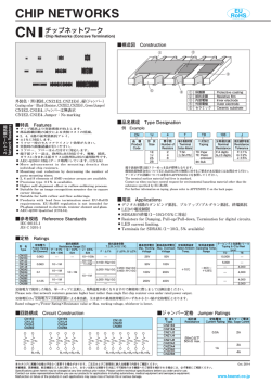
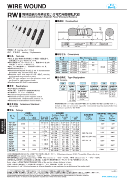
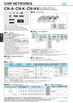
POWER TYPE
MO
MOX
EU
RoHS
塗装絶縁形酸化金属皮膜固定抵抗器
Coat-Insulated Fixed Metal Oxide Film Resistors
塗装絶縁形金属皮膜固定抵抗器
Coat-Insulated Fixed Metal Film Resistors
■構造図 Construction
C
②
③
④
⑤
φd
①
⑥
⑦
L
①
②
③
④
外装色:ブルーグレー Coating color:Blue gray
表示:カラーコード Marking:Color code
●
●
●
●
●
●
●
●
●
●
●
形 名
Type
MO
(X)
1/2
MO
(X)
1
MO
(X)
2
MO
(X)
3
汎用電力形抵抗器です。
難燃性塗装です。
(UL94 V-0相当品)
自動挿入が可能です。
各種フォーミングが可能です。
高信頼性。
欧州RoHS対応品です。
General purpose power type resistors.
Flame retardant coating. (Equivalent to UL94 V-0)
Automatic insertion is applicable.
Various types of formings are available.
High reliability.
P
roducts meet EU-RoHS requirements.
電力形抵抗器
High Power Type Resistors
MO(X)1/2C
MO(X)1C
MO(X)2C
MO(X)3C
Electrode cap
Lead wire
Resistive film
寸 法 Dimensions(mm)
C Max.
D
d(Nominal)
11.1
3.2±0.5
0.7
15.0
4.0±0.5
18.0
6.0±1.0
0.8
28.0
9.0±1.0
L
9.0±1.0
12.0±1.0
15.5±1.0
24.5±1.0
ℓ※
24Min.
30±3
38±3
Weight(g)
(1000pcs)
480
800
1,400
4,600
■品名構成 Type Designation
例 Example
MO
2
C
T631
A
品 種
Product Code
定格電力
Power
Rating
1/2 : 0.5W
1 : 1W
2 : 2W
3 : 3W
端子表面材質
Terminal
Surface Material
C : SnCu
二次加工
Taping &
Forming
下記参照
See table
below
包 装
Packaging
MO:塗装絶縁形酸化金属
皮膜固定抵抗器
Coat-insulated Fixed
Metal Oxide Film Resistors
MOX:塗装絶縁形金属
皮膜固定抵抗器
Coat-insulated Fixed
Metal Film Resistors
■二次加工対応表 Taping & Forming Matrix
アキシャルテーピング
Axial Taping
T52
T521
T631
○
ー
ー
○
○
ー
ー
○
○
ー
ー
ー
電極キャップ
リード線
抵抗皮膜
※ テーピング及びフォーミングによってリード寸法が異なります。
※ Lead length changes depending on taping and forming type.
■参考規格 Reference Standards
IEC 60115-4
JIS C 5201-4
EIAJ RC-2138
形 名
Type
Marking
⑤
Flame retardant insulation coating ⑥
Trimming line
⑦
Ceramic core
■外形寸法 Dimensions
■特長 Features
●
表示
難燃性絶縁塗装
トリミングライン
セラミック
D
潰しテーピング
Stand-off Axial Taping
L52
L521
L631
○
ー
ー
ー
○
ー
ー
ー
○
ー
ー
ー
103
A :アモパック
A :AMMO
R :リール
R :REEL
空欄:ボックス
Nil:BOX
J
公称抵抗値 抵抗値許容差
Nominal
Resistance
Resistance Tolerance
3 digits G: ±2%
J :±5%
環境負荷物質含有についてEU-RoHS以外の物質に対するご要求がある場合にはお問合せください。
テーピング及びフォーミングの詳細については巻末のAPPENDIX Cを参照してください。
Contact us when you have control request for environmental hazardous material other than the
substance specified by EU-RoHS.
For further information on taping and forming, please refer to APPENDIX C on the back pages.
L12.5A
○
ー
ー
ー
L15A
○
○
ー
ー
Lフォーミング
L Forming
L20A
L25A
ー
ー
○
ー
○
○
ー
ー
L30A
ー
ー
ー
○
L35A
ー
ー
ー
○
Uフォーミング
U Forming
U
○
○
○
ー
Mフォーミング
M Forming
M15
M20
M25
M15F
ー
ー
M15S
ー
ー
ー
M20E
M25C
ー
ー
ー
■定格 Ratings
形 名
Type
定格電力
Power
Rating
MO1/2C
0.5W
MO1C
1W
MO2C
2W
MO3C
3W
MOX1/2C
0.5W
MOX1C
1W
MOX2C
2W
MOX3C
3W
抵抗値範囲(Ω)
Resistance Range(E24)
G:±2%
10〜47k
10〜100k
5.1〜9.1
J:±5%
抵抗温度係数
T.C.R.
(×10−6/K)
10〜47k
10〜120k
10〜150k
±200
0.2〜9.1
最高使用電圧
Max. Working
Voltage
最高過負荷電圧
Max. Overload
Voltage
耐 電 圧
Dielectric Withstanding
Voltage
250V
400V
400V
350V
600V
500V
800V
500V
400V
E=√ ̄ ̄
P×R
E×2.5
500V
テーピングと包装数/アモ包装
Taping & Q'ty/AMMO(pcs)
T52A
T521A
2,000
—
T631A
—
1,000
1,000
—
—
500
—
—
—
2,000
—
—
1,000
1,000
—
500
—
—
1,000
—
1,000
—
定格周囲温度 Rated Ambient Temperature:+70℃
使用温度範囲 Operating Temperature Range:−55℃〜+200℃
定格電圧は √ ̄ ̄ ̄ ̄ ̄ ̄ ̄ ̄ ̄
定格電力×公称抵抗値による算出値、又は表中の最高使用電圧のいずれか小さい値が定格電圧となります。
Rated voltage=√ ̄ ̄ ̄ ̄ ̄ ̄ ̄ ̄ ̄ ̄ ̄ ̄
Power Rating×Resistance value or Max. working voltage, whichever is lower.
本カタログに掲載の仕様は予告なく変更する場合があります。ご注文およびご使用前に納入仕様書で内容をご確認ください。
車載機器、医療機器、航空機器など人命に関わったり、あるいは甚大な損害を引き起こす可能性のある機器へのご使用を検討される場合には、必ず事前にご相談ください。
Specifications given herein may be changed at any time without prior notice. Please confirm technical specifications before you order and/or use.
Contact our sales representatives before you use our products for applications including automotives, medical equipment and aerospace equipment.
Malfunction or failure of the products in such applications may cause loss of human life or serious damage.
Oct. 2014
www.koanet.co.jp
■負荷軽減曲線 Derating Curve
定格電力比(%)
Percent rated power
100
周囲温度70℃以上で使用される場合は、左図負荷軽減曲線に従って、定
格電力を軽減して御使用ください。
For resistors operated at an ambient temperature of 70℃ or above, a power
rating shall be derated in accordance with derating curve on the left.
80
60
40
20
0
-60 -40 -20 0 20 40 60 80 100 120 140 160 180 200 220 240
70
周囲温度 Ambient temperature(℃)
235
200
200
175
175
150
125
100
75
50
25
0
0
■耐久性(定格負荷) Load Life At 70℃ 1000h
+4
150
125
100
3W
(L30A)
75
50
1W
(L15A)
3W
(L30A)
2W
(L15A)
2W
(L15A)
0.5W
(L15A)
R/R(%)
表面温度上昇(℃)
Surface temperature rise
表面温度上昇(℃)
Surface temperature rise
■表面温度上昇 Surface Temperature Rise
+2
0
1W
(L15A)
+4
-4
-4
0.2
1
MO1
MO1
0
-2
100
MOX1
+2
-2
0.5W
(L15A)
25
0
25 0
50 25
75 50
100 75
定格電力比率
Power
定格電力比率 Power
rating ratio
(%) rating ratio(%)
MOX1
R/R(%)
-55
0.2 100
1
10
100 47k 1k
10k 47k
10
1k
10k
抵抗
値 Resistance(Ω)
抵 抗 値 Resistance
(Ω)
■性能 Performance
試験項目
Test Items
抵抗値
Resistance
抵抗温度係数
T.C.R.
過負荷(短時間)
Overload(Short time)
はんだ耐熱性
Resistance to soldering heat
端子強度
Terminal strength
温度急変
Rapid change of temperature
耐湿負荷
Moisture resistance
70℃での耐久性
Endurance at 70℃
難燃性
Flame retardant
1
0.5
1
0.5
試験方法
Test Methods
測定箇所は本体から10mm±1mmとする
Measuring points are 10mm±1mm from the end cap.
室温/100℃ up
Room temperature + 100℃
定格電圧×2.5倍又は最高過負荷電圧の低い方を5秒印加
Rated voltage×2.5 or Max. overload vol., whichever is lower, for 5s
260℃±5℃、10s±1s
リード線の外れ、端子のユルミのないこと。
—
No lead-coming off and loose terminals
Twist 360°
、5 times
1
0.5
−55℃
(30min.)
/+155℃
(30min.)5 cycles
±(5%+0.1Ω)
2
±(5%+0.1Ω)
2
外観に異常がなく、表示は
容易に判読できること。
No abnormality in appearance.
Marking shall be easily legible
—
イソプロピルアルコールの超音波洗浄を2分間行う
Ultrasonic washing with Isopropyl alcohol for 2 min.
出力Power : 0.3W/cm2、周波数 f : 28kHz、温度Temp : 35℃±5℃
—
耐炎性:本体に試験火炎を15秒あて、15秒取り除く、5サイクル
Flame test : The test flame shall be applied and removed for each
15 sec respectively to repeat the cycle 5 times.
過負荷耐燃性:定格電力の 2倍、4倍、8倍、16倍、32倍に相当する
電力(AC)を断線に至るまでそれぞれ1分間印加する。
但し、印加電圧は最高使用電圧の4倍を超えないこと。
Overload flame retardant : Power (AC) corresponding to 2, 4, 8, 16 and
32 times the power rating shall be applied for each 1min. until
disconnection occurs.
However the applied voltage shall not exceed the value of 4 times
the maximum operating voltage.
発炎しないこと及び自己
発炎しないこと。
No evidence of flaming or
self-flaming.
40℃±2℃、90%〜95%RH、1000h
1.5時間 ON/0.5時間 OFFの周期 1.5h ON/0.5h OFF cycle
70℃±2℃、1000h
1.5時間 ON/0.5時間 OFFの周期 1.5h ON/0.5h OFF cycle
■使用上の注意 Precautions for Use
●
●
装塗装が難燃性特殊塗料の為、外部衝撃に比較的弱いので取り扱いにご注意ください。 洗浄は最小限にしてください。洗浄直後は
外
多少塗装膜が弱くなりますので、十分に乾燥するまで塗装膜に外力を加えないでください。乾燥後、元の強度に戻りますので、洗浄
後約20分間は抵抗器の塗装膜に外力が加わらない様に配慮ください。特に基板の積み重ね等は、行わないでください。
Be careful to handle these resistors because outer coatings are comparatively weak to outer shock due to flameproof special coats.
Please wash them to a minimum. No external force is given to the coating films until they are well dried because the coating films
become weaker right after washing. The original strength will be returned after they are dried, so please pay attention not to apply
any external force onto the coating film of resistors for 20 minutes after drying. Especially no PC boards shall be piled up.
本カタログに掲載の仕様は予告なく変更する場合があります。ご注文およびご使用前に納入仕様書で内容をご確認ください。
車載機器、医療機器、航空機器など人命に関わったり、あるいは甚大な損害を引き起こす可能性のある機器へのご使用を検討される場合には、必ず事前にご相談ください。
Specifications given herein may be changed at any time without prior notice. Please confirm technical specifications before you order and/or use.
Contact our sales representatives before you use our products for applications including automotives, medical equipment and aerospace equipment.
Malfunction or failure of the products in such applications may cause loss of human life or serious damage.
Oct. 2014
www.koanet.co.jp
電力形抵抗器
High Power Type Resistors
耐溶剤性
Resistance to solvent
規格値 Performance Requirements
ΔR±(%+0.05Ω)
保証値 Limit
代表値 Typicals
規定の許容差内
—
Within specified tolerance
規定値内
—
Within specified T.C.R.
© Copyright 2026