
振れ調整式 RAホルダ - BIG Kaiser
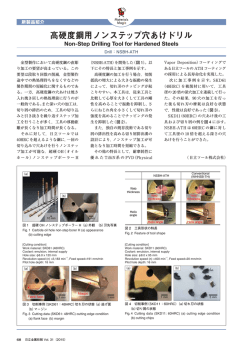
振れ調整式 RAホルダ 取扱説明書 RA HOLDER OPERATION MANUAL この度は、 振れ調整式RAホルダをお買い求めいただき誠にありがとうございま す。ご使用前にあたっては必ず本書をお読みいただき、ご使用される方がいつでも見 ることができる場所に必ず保管してくださいますようお願いいたします。 各部の名称 Runout adjustable Thank you for purchasing the RA HOLDER. Please read these instructions before use and keep them where the operator may refer to them whenever necessary. DESCRIPTIONS ① 調整リング Adjusting ring 調整リングは360°自由に回転させることができます。 You can rotate the adjusting ring 360 degrees. ③ ② ⑤ ② 基準マーク Reference mark 調整リングを回し、調整リングの(▽)マークを最も振れの大きな位置に合わせます。 On the adjusting ring a reference mark () is shown. Rotate the adjusting ring and align this reference mark at a point where the runout becomes least. ③ 調整スクリュ Adjusting screw 調整スクリュを回すことで、振れを調整することができます。 By rotating the adjusting screw, runout can be adjusted. ④ ロックボルト Locking bolt 調整リングには 3 ヶ所のロックボルトがあり、これを締め付けることで調整リン グを固定することができます。 On the adjusting ring, there are 3 locking bolts. By tightening them, the adjusting ring can be locked. ④ ⑤ チャック部 Tool Holder ① ミーリングチャックタイプとニューベビーチャックタイプがあります。用途に合 わせてご選択ください。(図はミーリングチャックタイプです。) New Hi-Power Milling Chuck and New Baby Chuck types are available. Choose one of these types depending on the application. The left drawing is of the New Hi-Power Milling Chuck type. 使用方法 調整作業は刃具を取り付けたホルダを工作機械の主軸に取り付けて行います。 切削工具の取り付けはチャック部の取扱説明書をご覧ください。 また工作機械の操作については、機械に付属のマニュアルをご参照願います。 工具シャンク部で振れを確認する場合 Adjusting should be done when the RA HOLDER and cutting tool are mounted into the machine spindle. Refer to the instruction manual of the tool holder for how to set the cutting tool into the tool holder. Concerning the operation of the machine tool, refer to the instruction manual of your machine tool. When the runout accuracy is adjusted at the shank part of the cutting tool 1) 3 ヵ所のロックボルトを緩め、調整リングをフリーにしてください。 Loosen the locking bolts and free the adjusting ring. ロックボルト(3ヵ所) Locking bolt(3 pcs) HOW TO USE 調整リング Adjusting ring 2) テストインジケータなどを工具シャンクに当て、 ホルダを手で回転させ、振れ幅を確認します。 Contact the test indicator on the shank of the cutting tool, rotate the holder manually and check the runout accuracy. 調整リングの基準マークを、振れがもっとも 大きくなる位置に合わせてください。 Align the reference mark at the max runout position. 3) 3 ヵ所のロックボルトを付属の L レンチで締め付け、調整リングを固定 します。このとき、ロックボルトを一気に締め付けず、均等に少しずつ 締め付けるようにしてください。 Tighten the 3 locking bolts with the included wrench and lock the adjusting ring. Tighten the 3 locking bolts evenly and gradually. 4) 付属の T レンチで調整スクリュを回すと、 振れが小さくなる方向に調整されます。 テストインジケータの値が振れ幅のちょ うど真ん中を指すところまで、調整スク リュを回してください。 By tightening the adjusting screw with the included T-wrench runout is minimized. Tighten the adjusting screw to the position where the value on the test indicator indicates the intermediate value. 調整スクリュは左右どちらからでも操作することができます。 The adjusting screw can be tightened from either side. 5) 最後にもう一度ホルダを手で回して、工具シャンクの振れを確認してください。 Rotate the RA HOLDER manually and check its runout accuracy. ■ 東 部 支 店 TEL048(252)1323 ■ 仙 台 営 業 所 TEL022(382)0222 ■ 北関東営業所 TEL0276(30)5511 ■ 南関東営業所 TEL046(204)0055 ■ 長 野 営 業 所 TEL0263(40)1818 ■ ■ ■ ■ ■ 中 部 支 店 TEL052(871)8601 ■ 広 島 営 業 所 TEL082(420)6333 静 岡 営 業 所 TEL054(654)7001 ■ 九 州 営 業 所 TEL092(451)1833 北 陸 営 業 所 TEL076(292)1002 ■ 海外営業本部 TEL072(982)8277 西 部 支 店 TEL06(6747)7558 岡 山 営 業 所 TEL086(245)2981 No.1014 切刃で振れを調整する場合 When the runout accuracy is adjusted at the cutting edge 刃長の長い切削工具をご使用になる場合などは、実際の切れ刃で確認されることをお奨めします。 この場合、テストインジケータで読み取れる振れ方向と全周での振れ方向が異なる場合がありますので、 下記の手順で振れ方向を補正する必要があります。補正の方法は刃数や振れの大きさによっても変わります。 When a long projection cutting tool is used, we recommend that the runout accuracy be adjusted at the actual cutting edges. In this case, the directions between the runout, which can be checked by a test indicator, and the runout of the circumference may be different. Then, the runout needs to be compensated referring to the following procedures. Compensation direction is changed depending on the number of cutting edges or runout amount. 【2枚刃の場合 In case of 2 cutting edges】 2 枚刃の場合は角度補正の必要はありません。高いほうの切れ刃に基準マークをあわせ、調整作業を行ってください。 In case of 2 cutting edges, the angle does not need to be compensated. Set the reference mark at the higher cutting edge and adjust the runout accuracy. 【3枚刃の場合 In case of 3 cutting edges】 図の①∼③を切削工具の切刃だとします。まずテストインジケータなどを使用し、各切刃の高さを測ります。そして最も低 い刃でゼロになるようにインジケータの目盛りを合わせてください。今仮に①が最も低く、ここをゼロに合わせたとします。 a) ②と③が同じ値になった場合は基準マークを②と③の真ん中に合わせてください。 b) ゼロが 2 ヵ所になる場合は、一番高い切刃に基準マークを合わせます。 c) ③より②の値が大きな場合、③/②=δとし、下のグラフから角度を読取ります。 ②から角度θだけ③の方向に回した位置に基準マークを合わせてください。 Taking ①, ② & ③ as cutting edges of the cutting tool for example, first measure the height of each cutting edge with the test indicator. Then, set the scale of the indicator to 0 at the lowest cutting edge.Taking ① as the lowest cutting edge, for example, set the scale of the indicator to 0 at ①. a) If ② & ③ are the same height, set the reference mark to the middle point of ② & ③. b) If 2 of 3 cutting edges are 0, set the reference mark to the highest cutting edge. c) If ② is higher than ③, find the angle from the below graph with the formula ③ / ② = δ. Set the reference mark to the position where the angle θ is rotated from ② toward ③. 【4枚刃の場合 In case of 4 cutting edges】 3 枚刃と同様に、最も低い切刃がゼロになるようにインジケータの目盛りを合わせてください。今①をゼロに合わせたものとします。 a) ②と④が同じ値になった場合は基準マークを③に合わせてください。 b) ゼロが二ヶ所になる場合、例えば ①と②の二ヶ所がゼロの場合は、③と④の真ん中に基準マークを合わせます。 c) ④より②の値が大きな場合、④/②=δとし、下のグラフから角度を読取ります。③を基準に角度θだけ②の方向に回した 位置に基準マークを合わせてください。 Same procedure as 3 cutting edges. Set the scale of indicator to 0 at the lowest cutting edge. Set ① at 0 for example. a) If ② & ④ are the same height, set the scale of the indicator to ③. b) If 2 of the cutting edges are 0, taking ① & ② as 0 for example, set the reference mark to the middle point of ③ & ④. c) If ② is higher than ④, find the angle from the below graph with the formula ④ / ②=δ. Set the reference mark to the position where the angle θ is rotated from ③ toward ②. 角度補正値グラフ Angle Compensation Graph 【3枚刃の場合 In case of 3 cutting edges】 40 30 20 10 0 0.0 40 角度 Angle θ(deg) 角度 Angle θ(deg) 50 0.2 0.4 0.6 係数 Modulus δ 0.8 1.0 【4枚刃の場合 In case of 4 cutting edges】 30 20 本体には5°ごとに目盛りを刻印しており ますので、角度合わせの目安としてご利用 ください。 On the tool holder, the reference is marked in 5 degree increments to help you adjust the angle. 10 0 0.0 0.2 注意事項 【調整作業について Adjusting】 ・調整スクリュは許容トルク以内で締め付けてください。また必ず付 属の工具をご使用ください。 ・Lレンチをパイプなどで延長したり、Tレンチで締め付けるところを Lレンチで締め付けたりは絶対にしないでください。 ・調整スクリュの許容トルクは右表をご覧ください。 ・Tighten the adjusting screw within the permissible torque range. In addition, be sure to use the included exclusive wrench for adjusting. ・Never use an extended L-wrench connected with a long pipe. Never tighten the adjusting screw with an L-wrench. ・Refer to the right table for the permissible torque range. 0.4 0.6 係数 Modulus δ 0.8 1.0 CAUTION 調整スクリュ許容トルク値 チャックタイプ Chuck Model ニューハイパワーミーリングチャック NEW Hi-POWER MILLING CHUCK ニューベビーチャック NEW BABY CHUCK HMC20S-NRA HMC25S-NRA HMC32S-NRA NBS 8-NRA NBS13-NRA NBS20-NRA 適合レンチ Wrench Model 許容トルク permissible torque range (N・m) CK-T4 8 CK-T2.5 3 CK-T3 6 ■ EXPORT DEPARTMENT TEL (+81)-72-982-8277

© Copyright 2026