
TECHNーCAL N。TE
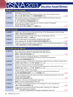
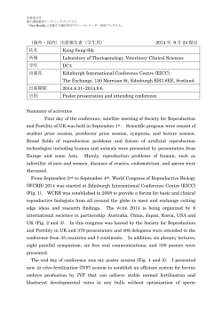
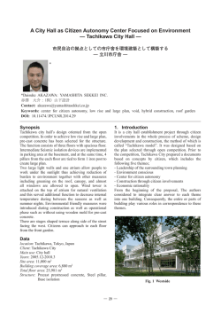
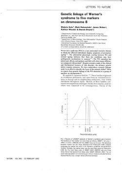
Magn Reson Med Sci,Vol.6,No.2,pp. 113-120,2007
TECHNICAL NOTE
Optilnized System Design and Comstructiom of a(Compact Whole‐ hand
Scammer for lDiagnosis of]Rheumatoid Arthritis
Shinya】
車ANDAl*,IIiroshi YosHIoKA2,sadanori ToMIHAl,TOmoyuki HAISH13,
and Katsulni KosEl
l動Mブ物 ″
cり rン
夕た冴みα
勾物 ″2が Phys,cs,t/ziソ c容,ゥ こ
ア 盈予
7-F―
F 7珍
″″θdαら7む冴た冴うら rう
α物を,Jθ5-8j7,,ブ
,pα″
2D年,α
iθ
r″
r,gttα
″cttrザ択α所?′
θ
tt
α
湾
″
初夕
れ
な角
rο
』
α
ο
Srο
れ,Massac乃倣F冴生 し,M
ダ
gノ,β
wル ら
3舟互R ttc乃 刀0′ο =れc。
, 殆 夕そ夕うo,力 pα″
gノ
(Rcceived January 29,2007;Accepted NItarch 28,2007)
We have developed a compact magnetic resonance(MIR)imaging scanner with perma―
nent lnagnet,gradient coil set,and radiofrequency(RF)collS Optilnized for whole―hand
examination for the diagnosis of rheumatoid arthritis(RA).The System weighs about
2,eXCluding the shiё
600 kg,and installation space is 2 1■
ld room.Hand exa■ linations of
normal volunteers and patients、
vith RA、vere performed using a 3D Tl―
、
veighted gradient―
echo(GRE)sequence and short TIinversion recovery 3D fast spin"echo(STIR-3DFSE)se―
quence, and anatonlical structures and various lesions of the hand caused by RA、 vere
clearly visualized in a 16-lnin exanlination,It was concluded that the systen■
could be used
for diagnosis of RA in even a small clinic.
Keywords:プ
ソ Rち
ぎ 鶴ate4″
coあ
Per碗
″Z夕 ″す初 agz夕 ち RF cο
Introduction
WIagnetic resonance(NIR)iIIlaging of the hand is
、
videly accepted as a very useful tool for diagnosing
rheumatoid arthritis(RA)。 13 HoweVer,examina―
tion using conventional、 vhole―body WttR imaging
scanners is painful for patients because they must
place their hand(S)in the center of the magnets.
One of the best solutions to this problem is the use
of a syste■l specially designed for imaging human
extremities,
For this reason and for economy, several such
commercially available WIR imaging systems have
been used for hand exanlinations to diagnose RA.4
Such systems are adequate for diagnosis and more
comfortable and convenient for the patient.Early
detection of RA is essential for drug therapy and
requires whole― hand exalnination because the
locations of lesions caused by RA in the hand
cannot be predicted.The usefulness of colnlnercial―
ly available WIR systems for imaging the extremities
is seriously limited because their ields of vie、
v
tt SER,ガ
ル ″物 ″すο,冴 α/れ rtをts
quires the development of anヽ 在R systenl for imag―
ing extrelnities that has a suttciently large FOV for
、
vhole―hand exanlination.
We have already reported and demonstrated the
ical ettcacy of an WIR scanner with a relatively
cli■
large FOV(abOut 20 cm X 20 cm)fOr wh01e―
hand
examinations,5,6 However,installation space(abOut
61n2)and tOtal weight(about 1500 kg)Of the sys―
teln are too large for its use in a small clinic.
In this study, we have developed a compact
、
vhole中hand MIR imaging scanner that requires only
a 2rn2 for installation, weighs about 600 kg, ex―
cluding the shield rooln,and can be used in even a
small clinic.
Compact Whole‐
hand Scanner
Figure l sho、vs an overview of the compact
、
vhole―
hand scanner we developed. It consists of
a permanent magnet(NEOMAX Co., Osaka,
Japan), gradient coil set, radiofrequency (RF)
OrObe,and portable WIR imaging console.7 Th
(FOV)are tOO Small to assess the hand and wrist magnet was placed in an RF shield room (1.4m
in one exanlination. Overcolling this problenl re― wide× 2 m high× 2 m deep)to preVent external RF
noise.The installation space for the entire system
ネ
Corresponding author,Phonc: +81-29-853-5214,Fax: +81-
29-853-5205,E―
mail:[email protected]
measured l■
1× 2 1n excluding the shield rooHl and
2111× 2 1n including the shield room.
114
S.Handa ct al
Figure 2A sho、 vs the permanent magnet: fleld
turns for the transverse coil and 30 turns for the
strength,0.21T at 24.5° C;gap,16 cHl;homogenei―
20 cHl× 12 cn■ di―
ty, 34.6 ppln over the 20 cnl×
ameter ellipsoidal volume(DEV); and Weight,
520 kg. The size of the homogeneous region、
vas
vhole hand of an adult
deterIIlined to include the、
B一Fe mag―
person. Because this magnet used Nd一
netic lnaterial,the temperature dependence of the
axial coil.
Grooves(1.l mm wide,2.2 mm deep)for the
gradient coil、vinding pattern、 vere lnilled on Bake―
lite plates 2.7 1nm thick by a numerically controlled
lnilling machine according to the numerical data
calculated for the gradient coil set. Polyethylene―
coated copper wire(1-mm diameter)Was used for
m a g n c t i c i e l d s t r e n g t h w a s a b o u t -C1.1 0 0thep coil、vinding.The
pm/°
To lninilnize the temperature drift of the magnetic
3-axis gradient coil assembly
VaS Inadc by piling the(3y and Gz coils on theく
ヽ
neld, a temperature controller、
colls.The DC resistance and self―
vith proportional―
integral―derivative(PID)contr01lers was used.
Figure 2B and C sho、
vs the planar gradient coils;
gradient coils are tabulated in Table l,
Two RF probes were developed for this system.
thc transverse(x and y)gradient coll、
vas designed
using thc target― fleld approach,8 and the axial(z)
A 14-turn solenoid (oVal aperture 6 cnl wide×
12 cm high and 22 cm long)was uSed for whole―
gradient coil,a genetic algorithm(GA),9 HoWever,
in both design lnethods,efFects from the pole pieces
hand ilnaging(Fig. 3A). An eight―
turn solenoid
、
vere not considered.10 The design parameters、vere:
magnet gap, 16 cln; target― Ileld regio■, 20 cIIl×
20 cIIl×12cm DEV;diameter of the current flo、
v―
ing region,36 cln;and number ofturns of、
vires,24
Fig.1. Overvie、v ofthe compact、 vhole‐
hand scan―
ner installed in our university hospital.
3x
inductance of the
Fig.3。 (A)Radiofrequency(RF)probC fOr a whole
hand.(B)LC circuit of(A).(C)RF probe for high‐
resolution wrist imaging.(D)LC circuit of(C).
Fig。2. (A)Perl■
anent l■agnet.(B)TranSVersc(x and y)gradient coll.(C)
Axial(Z)gradiCnt coil.The diameter of the gradient coils is 38 cm.
障Iagnetic Resonancc in Mcdical Scicnces
Compact WVhole Hand Scanneコ
Table l.
115
DC rcsistancc and sclf―
275
inductance of thc
gradicnt colls
lnductancc(μ
H)
Resistance(0)
3
1
5
6
4
5
8
8
8
x z
GQG
1.45
1.44
1.28
‐
︵ゆ聖 OΦじ aE oロ
Gradicnt coil
-a wthouttemp cOntrol
b Mlhtemp ccnlrol
―
才
/
(OVal aperture 7 cm wide× 9cm high and 7cm
iOng)Was used for high―
resolution wrist imaging
j m 。( m i n )
Fig.4.
Larmor frcqucncy drift of thc pcrmanent
(Fig.3C).Both SOlenoids were stored in RF shield
magnct measured whcn thc temperaturc controller
boxes for electrical stability.The LC circuits for the
RF probes are shown in Fig。 3B and D.
ExperiIIlents
、
vas on and ofF and、 vhilc a 3正
)gradicnt ccho imaging
sequcncc was running.Thc Larmor frcqucncy f(T)
、
vas plotted as a temperature T° C according to thc
equation f(T)=8.9174{1-0.0011(T-24.5)}.
NIeasurements of system performance
The temporal stability of the magnetic lleld of
the permanent magnet 、
vas measured using the
Larmor frequency of a water phantonl、
vhen the
temperature controller of the rnagnet、 vasturned on
and ofF.The Larmor frequency lneasurements、
vere
performed using an internal NWIR lock technique
previously described.7
The magnetic neld generated with the gradient
coilset was measured both in a free space and in the
magnet gap space. In the free space,the gradient
their hands into the RF coil for W【 R exallinations.
WIR exa■ linations for the norimal volunteers were
IR exaIIlinations of
performed on the left hand. い ブ
vere
perforined
on
both
hands.
patients、
Corona1 3D gradient―
echo Tl― weighted ilnages
(repetitiOn time[TR]=50 ms,echo time[TE]=
9 Hls,nip angle[FA]=60°
,and number of excita―
tions[NEX]=2)were aCquired with an image
matrix of 512× 256× 16 and FOV of 20。
48c11×
20。48c1lX6。 4cm. Thus, the total scan tilne 、 vas
coil assembly 、 vas constructed using alulninum
about 7 111in.Coronal short TI(inverSiOn tilne)in―
column spacers(15-mm diameter),and the magnet―
version recovery with 3D fast spin echo(STIR―
ic ield、vas measured using a Hall magnetometer
3DFSE)imageS Were acquired with an image matrix
(F.W.Bel1 6010,USA)when a COnstant current
of 256× 256× 8 in the same FOV. The scan pa―
ralmeters of the STIR-3DFSE sequence were:TR
=1000 1ns,TI=100■
ls,and efFective TE(TEer)=
(10A)was supplied to the gradient coils. In the
magnet gap space,the gradient coil set、
vas nxed on
the lnagnet pole pieces,and the lnagnetic fleld was
measured with att NMR Teslameter(MetrOlab
40 HIs,echo train length(ETL)=8,and NEX=2.
Thus,the total scan tilne was about 8.5 1nin.The
lnstruments, SA, Switzerland)when a cOnstant
TI、vas deterlnined for the fat signal so that it could
current(2A)was supplied.
be lninlmlzed.
Another 、 vater phantoHl 、 vas used to measure
linearity of the magnetic neld gradients and
homogeneity of the radiofrequency neld of the RF
coil for a hand. The phantom consisted of 32
acrylic cubic containers(lengths of the external and
internal edges: 2.4cm and 2.Oc■
1, respectively)
stacked in an 8 X 4 array,ealh container I11led、
vith
aqueous CuS04 SOlution.
Imaging experilllents
The WttR imaging systeIIl 、
vas approved by the
ethics conllnittee Of Our university hospital to be
used for clinical tests in our hospitale Subjects、 vere
ll healthy volunteers and 33 patients、
vith either
``suspected early RA,ル
``early RA,''or``advanced
High―resolution 3D GRE images of the wrist
were obtained with a smaller FOV using 3D gra―
dient echo sequences(TR=50m■
FA=60° ,and NEX=2 or 8).
s,TE=8 or 91ns,
Results and Discussion
WIcasurements of system performance
Figure 4 shows the Larmor frequency of the
magnet measured for about 8 hours when a 3D
GRE imaging sequence(TR=50 ms,TE=9 ms)
was running.The Larmor frequencyし
″り MHz Was
C)assuming
the
plotted against telmperature r(°
=8.ク77イ
following equation: ヮ
/rう
θFFrr一
{F一θ.θ
RA.ル After giving informed consent,the subjects
2イ.り〉
.This equation was based on a Larmor fre―
sat on a chair in front of the lnagnet and inserted
Hz at 24.5°
C measured in the
quency of 8.9174W圧
Vol.6 No.2,2007
S.Handa et al.
Z imml
Z imml
A
B
Fig。 5. (A)MagnetiC Ileld Bz produced by thc transvcrse gradicnt coil(x ory)CalCulatcd for thc xz
planc(y==0)in a frCC Spacc.(B)MagnCtiC neld Bz produccd by the transvcrsc gradient coll(x ory)
measured for the xz plane(y==0)in the lnagnct gap space.Thc contour lines are dra、
vn by thc O.1
Gauss step.
Fig.6. (A)MagnetiC neld Bz produced by thc axial gradient coll calculated for the xz plane(y==0)
in a free space.(B)MagnetiC Fleld Bz produced by the axial gradient colllncasurcd for the xz plane
vn by the O.l Gauss stcp. The largc
(y==0)in the magnct gap space. The contour lines are dra、
inhomogcneity seen at around z=30 1nnl and x=-100 111m in B is froln a lneasurcmcnt error but
docs not afFect our cxpcrilncntal results.
N E O N t t A X f a c t o r y a n d t h e a s s u m p t i o n t h a t t h e (B)magnetic Flelds in the xz plane(y=0)prOduced
temperature coettcient of tho lnagnetic nux density
by the Gx gradient coil;the lneasured gradient ield
of the permanent magnet material 、
vas -1100
、
vas larger than that calculated because the rnagnet―
C
.
ic
fleld、
vas enhanced by the lnagnetic materials of
ppm/°
As sho、vn in Fig.4,、 vhen the temperature con―
troller of the inagnet、
vas not used,the drift of the
Larmor frequency was about 2 kHz/hour,which
the permanent IIlagnet.
Figure 6 shows the calculated(A)and measured
may be attributable to both the Joule heat pro―
(]B)Inagnetic llelds in the xz plane(y==0)prOduced
by the Gz gradient coil;the lneasured gradient fleld
duced by thc gradient coil set and change in room
、
vas larger than that calculated because the lnagnet―
temperature.IIo、 vever,by setting the magnet tem―
ic lleld、
vas enhanced by the magnetic materials of
perature several degrees higher than room temper―
ature, the temperature drift、 vas stabilized、vithin
about O。 1°C for 8 hours, suttcient for the 7-and
the permanent magnet. The magnetic lleld 、
found to distort near the edges of the pole pieces,
8.5-Inin hand exanlinations.
Figure 5 shows the calculated(A)and measured
vas
、
vhere the Rose shinl、
vas attached.
Table 2 summarizes the emciency of the gradient
colls obtained froln the numerical calculation and
MIagnctic Resonancc in Mcdical Sciences
︲
︲
Compact Wholc Hand Scanncr
ン
ヽ
Table 2. Efnciency Of the gradicnt colls obtaincd from
numcrical calculation and expcrilncnts
熙
血
a∝
Ma謡
ap
ゴ
熙
calCulation Frec帥
熙
Gr齢
ン
0。 126(1.83)
0。 130(1.97)
0.276(1.54)
B
0.069
0.066
0.179
ヽ
G G G
0.0720(1.04)
0.0708(1.07)
0.1790(1.00)
Ettciencics of the gradient coils(G/cm/A).ValuCS in
parentheses are normalizcd using values from measure―
mcnts in free space.
the lneasurements described above.The calculated
ettciencies、 vere in good agreement、
vith the values
IIleasured in free space. IIo、 vever, the measured
ettcicncies in the lnagnet gap space、 vere l.5to 2.0
tilnes larger than those in free space.
The enhancement rates、
vere roughly explained
by the lnirror― current theory for the pole pieces.11
However, the enhancement rate of the Gz 、
vas
deinitely smaller than those of the Gx and Gy・
These data suggest that the eIFect of the magnet
yoke must be considered for the Gz coll because the
magnetic nux generated by one piece of the Gz coil
tries to decrease that generated by the other piece of
the Gz coll set through the yoke.1°
Figure 7 sho、 vs cross―sectionalilnages of the cube
array phantom acquired with 3D spin―
echo se―
quences(TR=100 ms,TE=16 ms,image matrix=
512× 256× 64, FOV=20。
48 cnl× 10。24 cln X 5.12
cm,and voxel size=0。 4mm×
0。
4mm×
0.8mm)。
The、 vater phantom was imaged、
vith positive and
negative readout gradients to lneasure the erects of
static magnetic neld inhomogeneity on image dis―
F
Fig.7. Cross― sectional planes of the watcr phan―
tom acquired with 3D spin echo scquences.A(xy
planc),B (xZ plane),and C (yz planc)、 vcre acquircd
、
vith the sequencc、 vith a positivc rcadout gradicnt
along the x direction,transverse dircction in A.D(xy
planc),】E(XZ planc),and F(yz planc)、 Vere acquircd
、
vith thc scquence with a negative rcadout gradicnt
along the x dircction.
tortion.
The most remarkable image distortion observed
in Fig.7 is caused by nonlinearity of the lnagnetic
that there is no problem in clinical applications.
lleld gradients. As sho、 vn by the cube size in the
WIR ilnages,the gradient neld strengths at the right
Figure 7A,C,E),and F demonstrates an increase
in image intensity froln the left to the right caused
and left edges ofthe phantom in Fig.7A,C,E),and
F are about 700/。
of those at the center of the
gradients. Ho、 vever, because the spatial variation
by a tuning circuit property of thl RF probe,
wherein the Q factOr Ofthe RF probeis around 300
of the image distortion is small,the image distor―
Because we used the long solenoidal RF coil,there
tion can be easily corrected and、
vill have no prob―
le■l in clinical applications.
The eniects of static rnagnetic fleld inhomogeneity
a n d t h e t u n i n g f r e q u e n c y r a n g e i s s m3 a0 l lk (H ∼
z).
、
vas no other detectable RF neld inhomogeneity in
the phantoln experilnents.
Imaging experilnents
on image distortion can be evaluated by comparing
the size of the cllbes acquired 、
vith positive and
negative readout Fleld gradients.Because the cubes
Figure 8 sho、vs coronal cross―seCtiOnal ilnages of
the left hand of a normal volunteer acquired、
vith
at the right edge(Fig. 7A)and left edge of the
Although ghost artifacts caused by lnapping of the
phantom in(Fig.7E))are identical,the size direr_
ences betwcen theln along the x direction(readOut
multiple spin echoes to the k―
direction)represent inhomogeneity of the static
magnetic fleld.IIo、 vever,the difFerence is so small
、
vere obtained.
Vol.6 No.2,2007
Tl―
weighted 3D GRE and STIR-3DFSE sequences.
space、 vere seen in
Fig.8B,12 sTIR ilnages with good fat suppression
Figure 9 sho、 vs high―resolution 2D ilnages select―
S.Handa et al.
Fig.8。 Corona1 2D ilnages selected froln a 3D dataset of a hand of a hcalthy
voluntccr.Images are acquired、vith(A)a31)gradicnt ccho scquence(repetition
time tTR]=50 nls,echo time[TEl=9 ms,and FA=60°
)and(B)a STIR-3DFSE
sequence(TR=1000 mls,inverslon timc[TI]=100 nlS,CfFective TE[TEcr]=40
ms,and ccho train length[ETL]=8).Thc ghOSt artifacts sccn in the short invcr―
sion time recovery(STIR)imageS are from altcrnativc mapping of thc multiplc
spin echoes in the k― space.
Fig.9. High― resolution Tl―
weightcd 2D ilnages selected fron1 3D datascts of a
hcalthy voluntccr.(A)Axia1 2D imagc of the distal radius.(B)COrOna1 2D imagc
of thc wrist.
ed from 3D image datasets acquired with 3D GRE
sequences(TR=50 ms,TE=8 ms,FA=60°
NEX=8 for Fig。
9A; TR=50 ms, TE=9n■
FA=60°
, and NEX=2 for Fig. 9B; acquisition
,and
s,
time=14 min).VOXCl size was O。 25× 0。5× 2 mm in
Fig,9A and O,35× 0.35× 21nm in Fig。 9B.
All ll healthy volunteers and 32 of the 33
Figure 10 sho、 vs corOnalilnages of both hands of
a patient with suspected early RA.These 2D ilnages
are selected from a 31)image dataset acquired by
STIR-3DFSE sequence.In Fig。
10,multiple areas
of high signal intensity、 vere seen along the nexor
and extensor tendons and at the metacarpal and
intercarpaljoints.These high signalintensities wer
vent successfulトッ
IR exalninations of
patients under、
v o of the patients、 vith
both hands and、 vrists. T、
consistent、vith lesions caused by early RA.
suspected early RA(n=10)Were diagnosed with
hand and more than 301nin for both hands.
Although this may appear long for the patients,
early RA based on STIR images.All patients with
early and advanced RA sho、
ved morphological or
signal intensity changes that enabled diagnosis of
RA froHI NItR imaging indings.
Measurement required about 161nin for one
fe、
v complaints 、vere raised because the patients
、
vere in relaxed positions. IIo、
vever, much higher
noise ratios(SNR)or ettCient pulse se―
s i g n a lt―
o―
障Iagnctic Rcsonancc in A/1edical Scienccs
Compact Whole Hand Scanner
Fig.10。
Corona1 2E)images selccted from 3D datasets Of both hands of a
patient with suspected carly rhcumatOid arthritis(RA)acquired with thc shOrt TI
CnVCrSiOn tinle)inversion recovery with 3D fast spin echo(STIR-3DFSE)sc―
quencc(repetition time[TR]=1000 ms,cchO timc invcrsion time[TI]=100 ms,
cfFectivc ccho tilne[TEcr]40 1ns,echo train lcngth[ETL]=8,matrix size=256×
256× 8,and voxel sizc=0.8mmXO.8mm×
8mm).SynOvitis and tcnosynovitis
are identilled in lnultiplc regions(arrOヽ
VS).
quences are needed to ilnprove patient through―
put.The straightfor、 vard solution to establishing a
higher SNR is to use a higher IIlagnetic lleld.If we
use a narro、ver Fnagnet gap and optilnized gradient
sets for the narro、v gap,、ve may construct a com―
pact hand scanner 、 vith a much higher magnetic
ield(abOut O.3T).
References
l. Klarlund N4t,Ostcrgaard M)Jcnsen KE,Madscn
」L, Skjodt ]H, Lorenzcn I. M【
agnctic rcsOnance
ilnaging, radiOgraphy, and scintigraphy of the
flnger joints:One ycar vf0110、
up of patients、
vith
2.
Condusion
We developed a colnpact MIR imaging systeln for
diagnosing rheumatoid arthritis in the hand,
including the wrist, by optilnizing the permanent
magnet, gradient coil set, RF coils, and pulse
sequences. The systeIIl weighs about 600 kg, and
installation space is about 2 1n2, eXCluding the
shield room.Because WIR exa■ linations of patients
、
vith RA suggested the clinical ettcacy of this sys―
tenl,we concluded that our system■could be used to
diagnose RA in even a small clinil.
Ackmowledgements
We lhank PrOfessor Takayuki Sunlida and Dr.
Satoshi ltoh fOr perlnitting us to use NItR images Of
a patient, MIro Natassaki Aoki and MIr. Eiichi
Sugiyalma of NEOWIAX Co.for constructing the
permanent magnet used for this study, and Drs.
Shin Utsuzawa and Andre、 vいッ
IcDo、vell for develop―
ing the image acquisition software.
early arthritis.The TIRA Group.Ann Rhcum Dis
2000;59:521-528.
Sugilnoto H,Takcda A,Masuyama J,Furuse M.
Early―stage rhcllmatoid arthritis: diagnostic ac―
curacy of¥R imaging.Radiology 1996;198:1853.
4.
192.
Sugilnoto H, Takeda A, Hyodoh K. Early,stage
rheumatoid arthritist prospective study Of thc
cttcctivencss of MR ilnaging for diagnosis.Radiol―
ogy 2000;216:569-575.
Evaluation of 10、 v_fleld cxtrelnity magnetic resO_
nance imaging(MRI),Amcrican Collcgc of Rhcu―
matology,2005.
5. Kurimoto T,Furuya T,Tomiha S,et alo Colnpact
Hand MRI Systcms using Pcrmancnt Magnets,In:
Proccedings of the 12th Annual NIeeting of the
ISMRM)Kyoto,2004;1638.
6. Yoshioka II, ItO s, Handa S, ct al. Lo、
v―
ield
compact magnctic rcsOnancc imaging system for
the hand and、 vrist in rhcumatoid arthritis.J Nfragn
Reson lmag 2006;23:370-376.
7. Haishi T, Uematsu T, Matsuda Y, Kosc K.
Devclopmcnt of a l.O T NIR nlicroscopc using a
Nd― Fe―B pcrmanent magnct. N【
agn Rcson lmag
2001; 19:875-880.
8. Turncr RA.Targct ield approach to optilnal coil
dcsign.J Phys D:AppI Phys 1986; 19:147-151.
9. Goldberg DE. Genctic algorithms in search,
optimization and machinc learning.First cditiOn.
Vol, 6 No.2,2007
S.Handa et al.
120
10.
Boston: Addison― Weslcy Longman Publishing,
1989.
Handa S,Okada F,Kose K.EIFects of maglletic
circuits on magnetic lleld gradicnts produced by
planar gradient coils. In:Proceedings of the 13th
Annual Meeting ofthe ISNIRNI,Miami,2005;851.
NIoon CH,Park]HW,Lee SY.A dcsign lnethod
inductance planar magnetic reso―
for ■linilnuHl―
nancc imaging gradient coils considering the pole―
piecc eIFect. Nfteas Sci Technol 1999; 10:N136N141.
12. Keller PJ,IIciserman JE,Fram EK,Rand SD,
to―view
Drayer BP. A Nyquist modulatcd ccho―
mapping scheme for fast spin― lcho imaging.NIagn
Reson Nlted 1995,33:838-842.
Magnetic Resonance in Medical Sciences


© Copyright 2026